Calculating Foot-candle Levels
This tutorial teaches you how to calculate the foot-candle levels in an area.
Open drawing E-3.1.
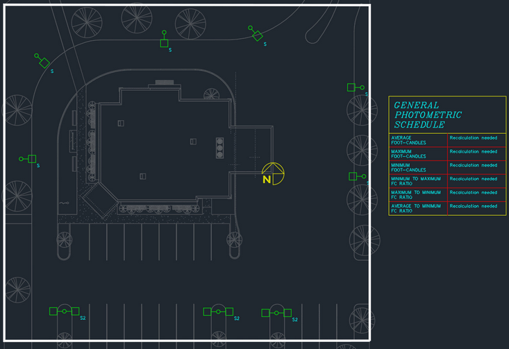
Insert Photometric Boundary
-
Run the
Insert General Photometric Calculation Area command. The Insert Photometric Calculation Area Boundary dialog box will open.
Ribbon:DM Electrical→Point-by-Point Photometrics→  Insert General Photometric Calculation Area
Pulldown Menu:DM Electrical→Point-by-Point Photometrics→Insert General Photometric Calculation Area -
Press the button to accept the default values and close the dialog box.
-
Follow the prompts at the command line to insert an area on the drawing, then press ENTER. The photometric calculation will be restricted to the area that is drawn.
-
Follow the prompt to insert the schedule next to the area.
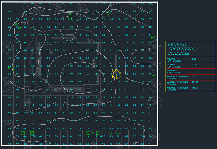
Calculate Foot-candle Levels
-
Run the
Calculate General Photometrics command. The Calculate Photometrics dialog box will open.
Ribbon:DM Electrical→Point-by-Point Photometrics→  Calculate General Photometrics
Pulldown Menu:DM Electrical→Point-by-Point Photometrics→Calculate General Photometrics -
Press the button to accept the default values.
The foot-candle levels will be calculated and displayed on the drawing. The schedule listing the uniformity ratios will be updated based upon the calculated values.