Ductwork in 3D
This tutorial teaches you how to use some of the 3D functions for ductwork.
Open drawing M-1.0.
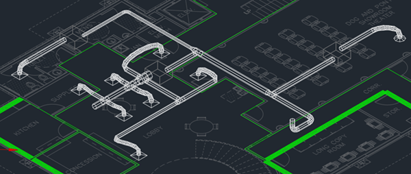
View Ductwork in 3D
-
Run the
Draw 3D Ductwork (Branch) command.
Ribbon:DM HVAC→3D-BIM→  Draw 3D Ductwork (Branch)
Pulldown Menu:DM HVAC→3D-BIM→Draw 3D Ductwork (Branch) -
Select a duct on the drawing. The 3D ductwork will be drawn.
-
Run the AutoCAD 2 Viewport command.
Ribbon: View→Model Viewports→Two: Vertical / Two: Horizontal
Pulldown Menu: View→Viewports→2 ViewPorts -
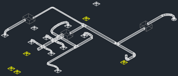
Run the AutoCAD SW Isometric command.
Ribbon: View→Named Views→SW Isometric
Pulldown Menu: View→3D Views→SW Isometric -
(Optional) Run the
Turn Duct Centerlines Off command to temporarily hide the duct centerlines.
Ribbon:DM HVAC→Layers→  Turn Duct Centerlines Off
Pulldown Menu:DM HVAC→Layer Management→Turn Duct Centerlines Off -
(Optional) Run the
Turn 3D Layers On (and Double Line Layers Off) command to temporarily hide double lines.
Ribbon:DM HVAC→Layers→  Turn 3D Layers On (and Double Line Layers Off)
Pulldown Menu:DM HVAC→Layer Management→Turn 3D Layers On (and Double Line Layers Off)
Export Ductwork for Collision Detection
-
Run the
Export Drawing to DWG File command. The Select filename to export 3D blocks to dialog box will open.
Ribbon:DM HVAC→3D-BIM→  Export HVAC Drawing to DWG File
Pulldown Menu:DM HVAC→3D-BIM→Export Drawing to DWG File -
Press the button.
The ductwork will be exported to a DWG file that can be opened in AutoCAD or used in Navisworks for 3D collision detection.
You can also use the
Offset the Origin for 3D Export
The alignment point acts as the origin when you export 3D ductwork, which can cause problems for some projects.
You can use the
Ribbon: ![]() Offset Alignment Point for 3D Export
Offset Alignment Point for 3D Export
Pulldown Menu: