Inserting a VAV System
This tutorial teaches you how to draft a duct system with VAV boxes.
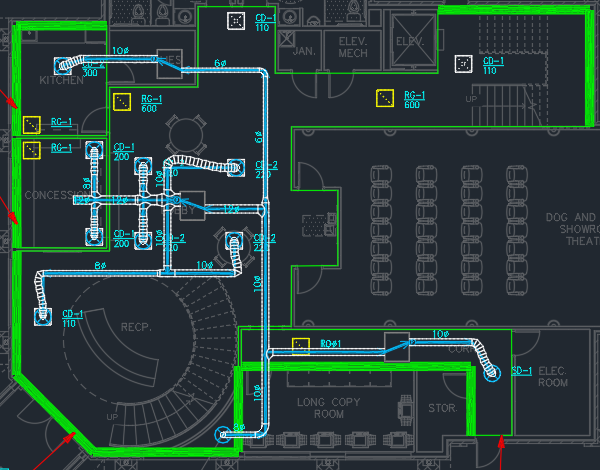
Open drawing M-1.0.
Erase Existing Ductwork
While inserting the VAV boxes and making other changes can be done with the existing system, it is easier to erase the ductwork, insert the VAV boxes, then redraw the ductwork going through the boxes.
-
Select all of the ductwork on the drawing. Other entities can be selected as well.
-
Run the
Erase Duct command.
Ribbon:DM HVAC→Ducts→  Erase Duct
Pulldown Menu:DM HVAC→Duct Centerlines→Erase Duct
The ductwork will be erased. Other selected entities will not be erased.
Insert VAV Boxes
-
Run the
Insert Equipment command. The Insert MEQ dialog box will open.
Ribbon:DM HVAC→MEQ→  Insert Equipment
Pulldown Menu:DM HVAC→Mechanical Equipment→Insert Equipment -
Make the following changes:
- Set Description to VAV.
- Set Width to 36.
- Set Length to 42.
- Set Height to 20.
- Set Elevation to 11.
- Set Elevation Location ▾ to Center of Equipment.
-
Press the button to close the dialog box.
-
Follow the prompts at the command line to insert the equipment on the drawing.
-
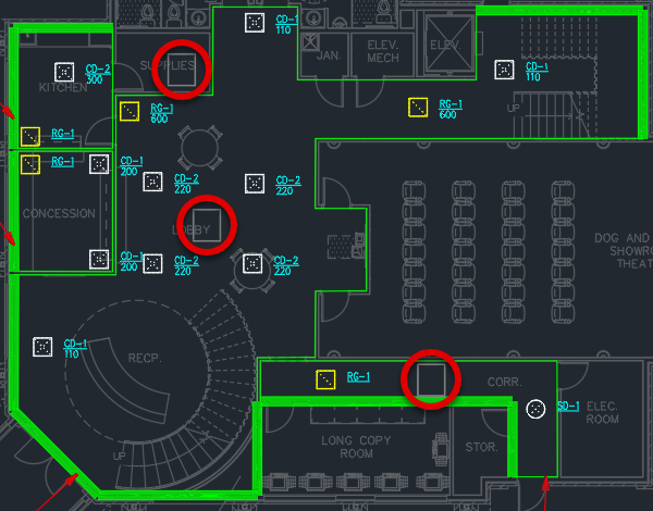
Use the standard CAD MOVE and COPY commands to insert a VAV box in the lobby, kitchen supply room, and corridor.
Insert Ducts and Diffuser Connections
-
Run the
Insert Duct command.
Ribbon:DM HVAC→Ducts→  Insert Duct
Pulldown Menu:DM HVAC→Duct Centerlines→Insert Duct -
Select a point inside the HVAC chase area.
-
Type V at the command line to insert a vertical duct. The Duct Information dialog box will open.
-
Set Starting Elevation to 13-6.
-
Set Ending Elevation to 11.
-
In Sizing Criteria, set Sizing Method ▾ to Static Regain.
-
Press the button to close the dialog box.
-
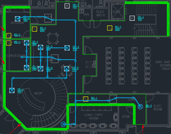
Continue inserting ducts for the corridor, lobby, concession area, and kitchen. Make sure ducts running through VAV boxes are drawn as separate segments.
-
Use the
Diffuser Connections commands to connect diffusers to the ducts.
Modify Ducts
-
Run the
Edit Multiple Ducts command.
Ribbon:DM HVAC→Ducts→  Edit Multiple Ducts
Pulldown Menu:DM HVAC→Duct Centerlines→Edit Multiple Ducts -
Select the ducts running through the VAV boxes. The Duct Settings dialog box will open.
-
Set Graphics ▾ to Transparent.
-
Press the button to close the dialog box.
-
Run the
Edit Multiple Ducts command.
Ribbon:DM HVAC→Ducts→ Edit Multiple Ducts
Pulldown Menu:DM HVAC→Duct Centerlines→Edit Multiple Ducts -
Select the ducts immediately after the VAV boxes. The Duct Settings dialog box will open.
-
In Sizing Criteria, set Sizing Method ▾ to Constant Pressure Drop.
-
Press the button to close the dialog box.
Calculate Airflow and Size Ducts
-
Run the
Ductwork Calculations command. The Duct Calculations dialog box will open.
Ribbon:DM HVAC→Ducts→  Ductwork Calculations
Pulldown Menu:DM HVAC→Calculations→Ductwork Calculations -
Set 🔘 Ducts to Use to Ducts in a System.
-
Press the button to select a duct system to calculate.
-
Select a duct on the drawing.
The airflow through the duct branch will be calculated. Each duct will be sized according to the required airflow and sizing parameters. Double lines will be drawn to reflect the duct sizing. Double lines will not be drawn for the ducts running through VAV boxes.