The Layers dialog allows you to customize the layers that are used in Design Master Plumbing. All devices, pipes, and schedules are inserted on a specific layer system. The layer systems allows you to put devices on different layers as necessary for drawing management.
The default layer systems included with Design Master Plumbing are New and Existing. One layer system that is often added is Demo. If a specific project is being done is specific phases, you could create a layer system for each phase.
There is also a layer system called General that is included in all lists. You cannot assign devices or pipes to this system. It is used to store all of the layers not associated with devices, such as schedules.
Each layer system consists of a group of layer keys. These keys are a mapping between layers and specific plumbing entities. The layer key identifies what Design Master Plumbing will put on the layer. The layer name assigned to each layer key does not need to be unique. You will notice that there are multiple layers used for more than one key in the standard Design Master Plumbing layer settings. The intention is to allow you more layer assignment options that you need, rather than fewer.
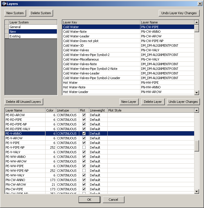
Layer Systems (Top Left)
Layer System: This is a list of layer systems currently defined. Use the New System button to create a new layer system.
Layer Keys (Top Right)
Layer Key: This is a non-editable field that lists all the fixed Design Master Plumbing layers as they are defined internally to Design Master.
Layer Name: For each layer listed in the Layer Key, select one layer from the pulldown list of layers. These layers are defined in the lower section of the dialog box.
Layers (Bottom)
Layer Name: This is where the layers are first defined. This list of layers includes every layer used by any layer system
Color: This is the AutoCAD color number for the layer. Click on this box and the color palette will be displayed.
Line Type: This is the AutoCAD line type. Click on this box and the line type list will appear.
Plot: Check this box is this layer is to be plotted. Otherwise, it will be entered as a non-plotting layer.
Lineweight: This is the AutoCAD line weight for the layer. Click on this box and the line weight list will appear.
Plot Style: This is the AutoCAD plot style for the layer. This is applicable only if plot styles are defined.