For branch circuits, voltage drop fluctuates along the circuit depending upon the wire length and cumulative load at each device. While calculating the voltage drop at each device would yield the most accurate results, ElectroBIM cannot trace the path of the circuit itself. Instead, the software approximates the total voltage drop by measuring the distance from the panel to each device on the circuit, taking the average distance, then calculating the total load at that distance as though it were a circuit with a single device.
As a result of this method, the following shared parameters will display the average panel-to-device distance when there are multiple devices on the circuit:
- DMEN_Circuit_Length
- DMET_Circuit_Length_ft
- DMET_Circuit_Length_m
- DMEN_Feeder_Length
- DMET_Feeder_Length_ft
- DMET_Feeder_Length_m
This article details different circuiting scenarios where the ElectroBIM calculation method works well, as well as scenarios where it does not. If you’re calculating voltage drop for a circuit that resembles one of the unfavorable scenarios, we recommend using Revit’s length measurement (which will give the distance to the farthest device on the circuit) or setting the length manually.
These scenarios use 120V receptacles with 0.18 kVA load, spaced at 100′ intervals with #10 wire.
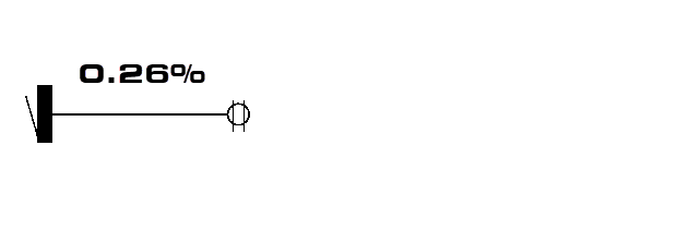
Single Device
For circuits with a single device, the actual calculation and the ElectroBIM calculation would be the same. The full load is concentrated in one location that matches the actual location of the device.
Multiple Devices in a Straight Line
For multiple devices, voltage drop would double, triple, etc., as devices are added to the circuit, and the actual calculation would sum the voltage drop along each wire.
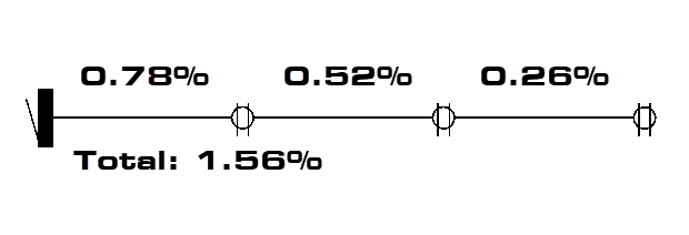
ElectroBIM would instead take the total load (0.18 * 3 = 0.54 kVA) and calculate voltage drop using the average panel-to-device distance:
(100′ + 200′ + 300′) / 3 = 200′
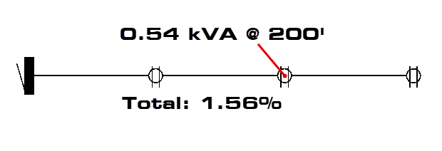
While the figures used in the calculation would differ, the results would be the same.
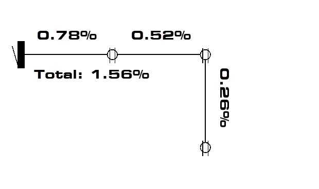
Multiple Devices Not in a Straight Line
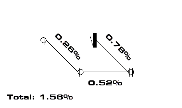
For the actual calculation, voltage drop is unaffected by the device placement if the wire lengths are the same. Therefore, the scenario below would have the same results as the “Straight Line” scenario above.
When changes in the angles are small, the ElectroBIM calculation will return accurate results. For example, a group of receptacles in a room will have an average panel-to-device distance somewhere in the middle of the group; the tighter they are clustered, the more accurate the results will be.
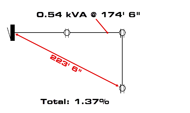
As the angles become more extreme, the ElectroBIM calculation becomes less reliable. If the project in this scenario were configured to measure wire lengths at right angles, it would still yield the same results. But if the lengths were measured along straight lines, the software would underestimate voltage drop for the circuit.
(100′ + 200′ + √[100’² + 200’²]) / 3 ≈ 174′ 6″
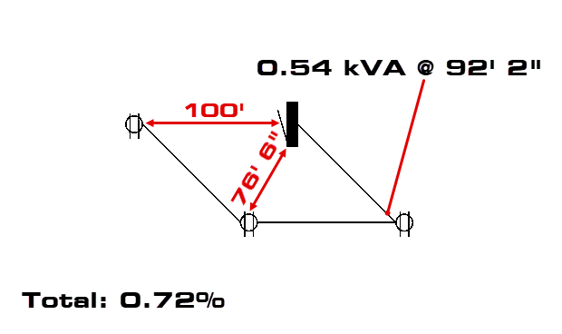
The differences become even more pronounced when devices on a single circuit begin to encircle the panel, as they might with site lighting. Again, the actual calculation would produce the same results as if the devices were in a straight line.
The ElectroBIM calculation, however, would ultimately calculate an average panel-to-device distance far below what is needed to make an accurate approximation (the example below assumes lengths are measured along straight lines).
(100′ + 76′ 6″ + 100′) / 3 ≈ 92′ 2″
In this situation, we would recommend using Revit’s length measurement (which would give the distance to the farthest device on the circuit) or setting the length manually.