This article covers two separate topics. The first is the new Copy and Increment Circuits command that we added. The second is the new One Line Devices that replace panels in the new release.
Imagine you have a row of ten rooms, each identical to the last. Each room has a light fixture in the middle and a receptacle on each wall. You really want to do one room just right--loops in the correct location, labels arranged nicely--and then copy it and be done. But wait, there is one minor little difference. The circuits that the light fixture and the receptacles are on are different for each room. If you copy the devices, the new instances will be uncircuited, and all of your work arranging loops will be lost.
This situation is exactly what we had in mind when we implemented Copy and Increment Circuits for this release. With this command, you select a group of devices to copy. Typically, when devices are copied, all of the loops are erased and the newly inserted devices are uncircuited. This command keeps all of the loops during the copy, and gives you an opportunity to recircuit all of the devices.
 The window at the right is the one used to select the new circuits for the devices. After you select the location for the copied devices, you are presented with a list of all the circuits that devices you copied were on. You now have the opportunity to map each circuit to a new panel and circuit. Design Master will automatically move all of the copied devices that were previously on the old circuit to the new circuit for you. All of the loops that you copied will be retained. All of the circuit labels and homeruns will be updated to match the new circuits of the devices.
We hope that this feature will be useful in any projects where room layouts are repeated.
The new version of Design Master replaces what were previously just panels with a concept that we like to call One Line Devices. These represent anything that you might find a one line diagram. Panels and transformers are still there. But we have now added:
 Panels
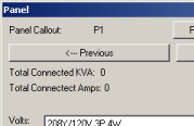
Panels are what we used to have before, but they have been greatly enhanced in this new release. For starters, the upstream transformer definition has been taken out of the panel and is now its own separate device. The next section talks more about transformers. You can see the revised Panel window by clicking on the picture to the right.
The main disconnect type of a panel can be specified as Main Lugs Only, Breaker, or Fused Switch. When the panel is drawn on the one line diagram, the setting here for the disconnect type is reflected in the graphics on the drawing.
The number of poles can now be any number. You can easily create 60, 84, or 126 pole panels.
The feeder specification for the panel has been improved in a number of ways. First, you can select a custom conduit size for the feeder. Also, the sizing of the wire is a little more intelligent. Previously, if the Conductor Amps was set to Size Automatically, it looked only to the Upstream OCP for the size of the wire. If the Upstream OCP happened to be set to N/A, then you had to manually set the Conductor Amps. Now, it will at the Bus Amps and Main Disconnect Amps for the size of the wire. If one of those is set to an appropriate value, it will use that for the wire size. Only after exhausting those locations will it require that you size it automatically. Of course, you always have the option to explicitly override the default sizing.
 Transformers
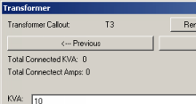
Transformers have been pulled out of the panel definition and are now their own separate device type. The new Transformer window is shown at the right. The only other new feature for transformers is that you can now have more than one device connected to them. The default is to allow 10 connections, but you can increase that if you find you need more.
Switchboards, bus gutters, bus ducts, wireways, and motor control centers are very similar to each other and to panels. Each of these are slightly different devices and as a result have a slightly different set of options used to specify them. The one difference from panels that they all share is how they are circuited.
Panels are defined with a certain number of poles. The odd poles go on the left; the even poles go on the right. If you have a three pole breaker, it takes up three poles in the panel.
These devices don't work like that. Instead, they have what are called positions, taps, starters, or lugs, depending upon the type of device. These positions are number sequentially, starting at 1 and working up from there. Each position corresponds to a single breaker of any size. It can be a single pole, two pole, or three pole breaker. All take up only one position.
 Switchboards
The only difference between a switchboard and a panel is that switchboards have positions and panels have poles. Other than that, they are exactly the same.
 Bus Gutters / Bus Ducts
Bus gutters and bus ducts are similar to panels, except that they are missing options for the main disconnect, neutral, and IG bus.
 Wireways
Wireways are missing bus amps in addition all of the same options as bus gutters.
 Motor Control Center
Motor control centers are like switchboards, though they have starters instead of positions.
 Enclosed Breakers / Disconnects
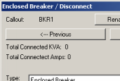
There are times when it is necessary to include a breaker in a one line diagram that is not associated with a panel. In this situation, there are three types of individual breakers: enclosed breakers, disconnects, and fused disconnects. The different types are represented with different graphics on the one line diagram.
 UPS's
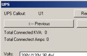
UPS'sThis release of Design Master adds two new devices, UPS's and transfer switches, that can have two upstream connections instead of just one. The load connected to these devices is transferred upstream to both connected devices to allow for proper sizing. The fault calculation is performed along both upstream branches. The worst case value is used at these devices and passed along to the ones below them.
 Generators
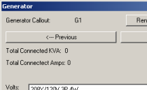
Typically, one line devices are fed from another one line device or the utility. Now, they can also be fed from generators. These devices sit at the top of the one line tree, providing power for the devices below. You are required to enter a fault for the generator so that the fault below it can be calculated.
 Transfer Switches
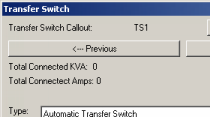
Transfer switches, like UPS's, can have two sources. They have the option to be set as either an automatic or a manual transfer switch.
That is it for One Line Devices. There are actually more similarities between the devices than differences, but those differences are important. In the next article, we will take a look at how all of the connections between the devices can be graphically displayed with the new One Line Diagram component of Design Master.
©2001-2023, Design Master Software, Inc