Circuit Types

Allows you to customize the circuit types available to be used for circuits. Circuit types inform the graphics and labels used when circuits are inserted on the riser diagram, as well as the cable types and sizes used in labels and during voltage drop calculations.
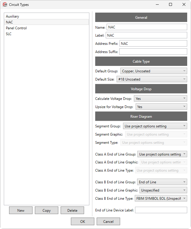
Opens the Circuit Types dialog box:
Circuit Types Dialog Box
-
Types ☰ All of the circuit types available in the project, listed alphabetically.
-
Adds a circuit type to the list with default settings.
-
Adds a circuit type to the list with values copied from the selected circuit type.
-
Removes the selected circuit type from the list.
General
-
Name: The name of the circuit type that is displayed in fields and lists.
-
Label: The label displayed for the circuit type in shared parameters and schedules, and displayed with the circuit number in circuit lists and voltage drop schedules.
-
Address Prefix: Text added before the circuit number in the device address.
-
Address Suffix: Text added after the circuit number in the device address.
Cable Type
-
Default Group: ▾ The cable type for the circuit type. Circuits set to size automatically will use cables of the specified type. The values in this list are based upon the Cable Types command.
-
Default Size: ▾ The default cable size for the circuit type. Cable sizes below this size can be chosen manually in the Circuit Edit command, but they will not be used when sizing automatically.
Voltage Drop
-
Calculate Voltage Drop: ▾ Whether circuits are included in voltage drop schedules and calculations.
-
Upsize for Voltage Drop: ▾ Whether automatically sized circuits will be upsized when the voltage drops below the Minimum circuit voltage specified in the Project Options command.
Riser Diagram
-
Segment Group: ▾ The graphic category used for the circuit type when circuits are inserted on the riser diagram. The groups available are based upon settings in the Riser Diagram Wire Graphics command.
- Use project options setting The Default circuit segment group ▾ specified in the Project Options command will be used.
-
Segment Graphic: ▾ The graphic family used for the circuit type when circuits are inserted on the riser diagram. The values in this list are based upon the Riser Diagram Wire Graphics command and the selected Segment Group ▾.
-
Segment Type: ▾ The graphic type used for the selected Segment Graphic ▾.
-
Class A End of Line Group: ▾ The graphic category inserted on the riser diagram after the last device on class A circuits. The groups available are based upon settings in the Riser Diagram Device Graphics command.
- Use project options setting The Default class A end of line graphic group ▾ specified in the Project Options command will be used.
-
Class A End of Line Graphic: ▾ The riser diagram graphic family inserted on the riser diagram after the last device on class A circuits. The values in this list are based upon the Riser Diagram Device Graphics command and the selected Class A Group ▾.
- Use project options setting The Default class A end of line graphic ▾ specified in the Project Options command will be used.
-
Class A End of Line Type: ▾ The riser diagram graphic type used for the selected Class A Graphic ▾.
-
Class B End of Line Group: ▾ The graphic category inserted on the riser diagram after the last device on class B circuits. The groups available are based upon settings in the Riser Diagram Device Graphics command.
- Use project options setting The Default class B end of line graphic group ▾ specified in the Project Options command will be used.
-
Class B End of Line Graphic: ▾ The riser diagram graphic family inserted on the riser diagram after the last device on class B circuits. The values in this list are based upon the Riser Diagram Device Graphics command and the selected Class B Group ▾.
- Use project options setting The Default class B end of line graphic ▾ specified in the Project Options command will be used.
-
Class B End of Line Type: ▾ The riser diagram graphic type used for the selected Class B Graphic ▾.
-
End of Line Device Label: The label used for end-of-line devices on circuits.
Default values for most settings in the Riser Diagram section can be viewed and modified in the Riser Diagram: Circuits Project Options and Riser Diagram: End of Line Project Options sections.