Project Options

Allows you to control the output of FireBIM to match your preferred standards.
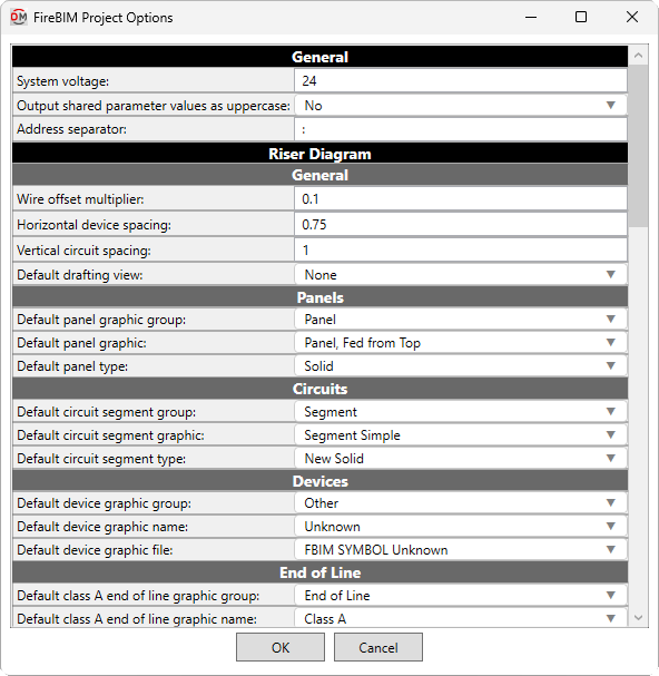
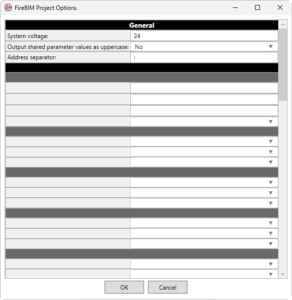
Opens the FireBIM Project Options dialog box:
FireBIM Project Options Dialog Box
Editing a Setting
To edit an option setting, select the Value ☰ in the list and enter a new value.
Press the button to save your changes.
General
-
System voltage: The nameplate voltage of the fire alarm system. This value is displayed in the voltage drop calculation schedule.
-
Output shared parameter values as uppercase: ▾ The format used for the case of default shared parameter values. User-specified values always use the text exactly as input by the user.
- Yes Shared parameters use all uppercase letters for fixed values.
- No Shared parameters use a mix of uppercase and lowercase letters for fixed values.
-
Address separator: Text used to separate the panel name, circuit, and device address number for the FBIM_Address shared parameter.
Riser Diagram
General
-
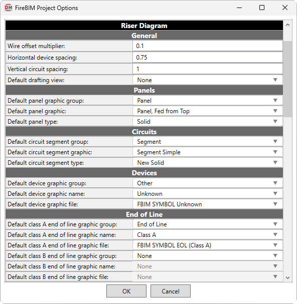
Wire offset multiplier: The multiplier used to determine the default distance between circuit elements. This setting affects spacing between devices, the default distance between circuits inserted using the Circuit Insert command, and the distance between wrapped sections of a circuit. It also affects the offset distance when using the Segment Offset command.
-
Horizontal device spacing: The minimum horizontal distance between devices on a circuit. Spacing between devices may be greater than this value to make room for large device symbols or to support the specified Wire offset multiplier.
-
Vertical circuit spacing: The vertical distance between wrapped sections of a circuit, and between circuits when multiple circuits are selected using the Circuit Insert command.
-
Default drafting view: ▾ The drafting view onto which device graphics will be inserted when using the Panel Insert command in a model view.
- None You will be prompted to select a drafting view each time you insert a device.
- Specific drafting view The device graphic will be added to the drafting view chosen from the list. The values in this list are based upon the drafting views in the project.
Panels
-
Default panel graphic group: ▾ The graphic category used by panels. The groups available are based upon settings in the Riser Diagram Device Graphics command.
-
Default panel graphic: ▾ The graphic family used by panels. The values in this list are based upon the Riser Diagram Device Graphics command and the selected Default panel graphic group ▾.
-
Default panel type: ▾ The graphic type used for the selected Default panel graphic ▾.
Circuits
-
Default circuit segment group: ▾ The segment graphic category used by circuit types. The groups available are based upon settings in the Riser Diagram Wire Graphics command.
-
Default circuit segment graphic: ▾ The segment graphic family used by circuit types. The values in this list are based upon the Riser Diagram Wire Graphics command and the selected Default circuit segment group ▾.
-
Default circuit segment type: ▾ The segment graphic type used for the selected Default circuit segment graphic ▾.
Devices
-
Default device graphic group: ▾ The graphic category used by devices. The groups available are based upon settings in the Riser Diagram Device Graphics command.
-
Default device graphic: ▾ The graphic family used by devices. The values in this list are based upon the Riser Diagram Device Graphics command and the selected Default device graphic group ▾.
-
Default device type: ▾ The graphic type used for the selected Default device graphic ▾.
End of Line
-
Default class A end of line graphic group: ▾ The graphic category inserted on the riser diagram after the last device on class A circuits. The groups available are based upon settings in the Riser Diagram Device Graphics command.
- None No end of line graphic will be inserted.
-
Default class A end of line graphic: ▾ The graphic family inserted after the last device on class A circuits. The values in this list are based upon the Riser Diagram Device Graphics command and the selected Default class A end of line graphic group ▾.
-
Default class A end of line type: ▾ The graphic type used for the selected Default class A end of line graphic ▾.
-
Default class B end of line graphic group: ▾ The graphic category inserted on the riser diagram after the last device on class B circuits. The groups available are based upon settings in the Riser Diagram Device Graphics command.
- None No end of line graphic will be inserted.
-
Default class B end of line graphic: ▾ The graphic family inserted after the last device on class B circuits. The values in this list are based upon the Riser Diagram Device Graphics command and the selected Default class B end of line graphic group ▾.
-
Default class B end of line type: ▾ The graphic type used for the selected Default class B end of line graphic ▾.
Circuits
General
-
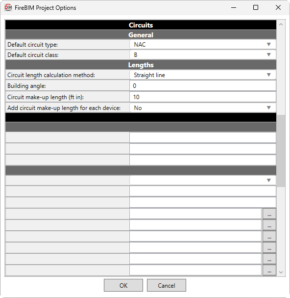
Default circuit type: ▾ The default circuit type used by circuits. The values in this list are based upon the Circuit Types command.
-
Default circuit class: ▾ Whether circuits are considered class A or class B when calculating circuit length and voltage drop.
Lengths
These options set the default values that appear in the
Battery Calculations
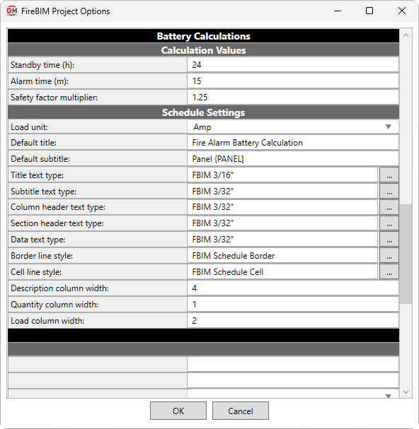
Calculation Values
For more information about the battery calculations, visit the Battery Calculation Basis article in the knowledge base.
-
Standby time: The minimum duration in hours batteries must be able to power devices while in standby mode.
-
Alarm time: The minimum duration in minutes batteries must be able to power devices while in alarm mode.
-
Safety factor multiplier: The safety factor by which battery calculation subtotals are multiplied per NFPA 72 10.6.7.2.14.
Schedule Settings
These options are used to customize battery calculation schedules created using the Battery Schedule command.
For text types and line styles, you can press the button to select from those present in the project.
If you manually enter a text type or line style that does not exist in the project, a text type or line style with that name will be created from one of the FireBIM defaults.
-
Load unit: ▾ Whether schedule load values are displayed in amps or milliamps.
-
Default title: The default text that is entered in the Title field when running the Battery Schedule command.
-
Default subtitle: The default text that is entered in the Subtitle field when running the Battery Schedule command. You can use the text
{PANEL}to automatically generate the name of the panel. -
Title text type: The default text type for schedule titles.
-
Subtitle text type: The default text type for schedule subtitles.
-
Column header text type: The default text type for schedule column headings.
-
Section header text type: The default text type for schedule section headings such as Devices and Subtotal.
-
Data text type: The default text type for schedule data and notes.
-
Border line style: The line style used to draw the schedule border.
-
Cell line style: The line style used to draw the lines between schedule cells.
-
Description column width: The width of the Description schedule column.
-
Quantity column width: The width of the Quantity schedule column.
-
Load column width: The width of the Unit Standby, Total Standby, Unit Alarm, and Total Alarm schedule columns.
Voltage Drop
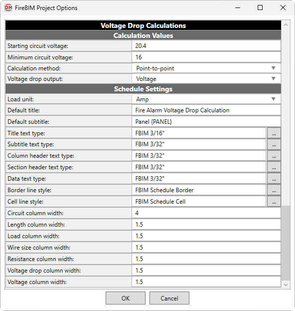
Calculation Values
For more information about the voltage drop calculations, visit the Voltage Drop Calculation Basis article in the knowledge base.
-
Starting circuit voltage: The starting voltage used when calculating voltage drop.
-
Minimum circuit voltage: The minimum voltage allowed on circuits. Circuits with devices that drop below this voltage will be upsized if able. Calculated voltages below this value will be highlighted in voltage drop schedules.
-
Calculation method: ▾ How voltage drop is calculated and displayed in schedules.
- Point-to-point Voltage drop is calculated and displayed based upon the cumulative load and circuit length at each device on the circuit.
- End-of-line Voltage drop is calculated and displayed based upon the total circuit load and total length.
-
Voltage drop output: ▾ How voltage drop values are displayed.
- Voltage Displays the voltage drop in volts.
- Percentage Displays the voltage drop as a percentage of the starting voltage at the device or the starting voltage for the circuit, depending upon the selected Calculation method ▾.
- Voltage / Percentage Displays the voltage drop in volts, and as a percentage in parentheses.
Schedule Settings
These options are used to customize voltage drop schedules created using the Voltage Drop Schedule command.
For text types and line styles, you can press the button to select from those present in the project.
If you manually enter a text type or line style that does not exist in the project, a text type or line style with that name will be created from one of the FireBIM defaults.
-
Load unit: ▾ Whether schedule load values are displayed in amps or milliamps.
-
Default title: The default text that is entered in the Title field when running the Voltage Drop Schedule command.
-
Default subtitle: The default text that is entered in the Subtitle field when running the Voltage Drop Schedule command. You can use the text
{PANEL}to automatically generate the name of the panel. -
Title text type: The default text type for schedule titles.
-
Subtitle text type: The default text type for schedule subtitles.
-
Column header text type: The default text type for schedule column headings.
-
Section header text type: The default text type for schedule section headings.
-
Data text type: The default text type for schedule data and notes.
-
Border line style: The line style used to draw the schedule border.
-
Cell line style: The line style used to draw the lines between schedule cells.
-
<Column> column width: The width of the specified schedule column. For example, Circuit column width sets the width of the Circuit schedule column.