Family Edit

Allows you to view and edit additional fire alarm device information added to a family.
Opens the Family Edit dialog box. The information displayed in the dialog box is based upon the Device Type. The dialog box for each device type is described below.
-
Device Type: Controls how the family is handled by FireBIM. Each device type provides a different set of values that can be specified.
- Fire Alarm Device The Revit Family Category ☰ is set to Fire Alarm Devices.
- Fire Alarm Panel The Revit Family Category ☰ is set to Electrical Equipment and Part Type ▾ is set to Other Panel.
-
List ☰ All of the family types in the family, listed alphabetically.
You can select multiple types in the list using the SHIFT or CTRL key.
-
Press this button to rename the family type selected in the list.
-
Press this button to copy the settings from a family type to the family type(s) selected in the list.
Fire Alarm Device
These values are displayed when the Device Type is set to Fire Alarm Device.
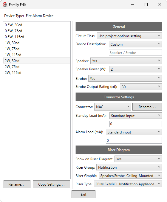
General
-
Circuit Class: ▾ Whether circuits to which the device is connected are class A or class B when calculating circuit length and voltage drop.
- Use project options setting The Default circuit class ▾ specified in the Project Options command will be used.
-
Device Description: ▾ The description displayed in calculation schedules for the device.
- Family - Type The device family and type will be used.
- Based on parameter The value for the specified parameter will be used. Press the button to select a parameter. Visit the Using Non-FireBIM Parameters for FireBIM Settings article in the knowledge base for more information.
- Custom Enter a device description in the field provided.
-
Speaker: ▾ Whether the device has a speaker.
- Speaker Power: ▾ The wattage of the speaker. If Speaker ▾ is set to No, this field is disabled.
- Specific wattage The wattage is set to the specific wattage chosen from the list.
- Based on parameter The value for the specified parameter will be used. Press the button to select a parameter. Visit the Using Non-FireBIM Parameters for FireBIM Settings article in the knowledge base for more information.
- Custom Enter a custom value in the field provided.
- Speaker Power: ▾ The wattage of the speaker. If Speaker ▾ is set to No, this field is disabled.
-
Strobe: ▾ Whether the device has a strobe.
- Strobe Output Rating: ▾ The candela rating of the strobe. If Strobe ▾ is set to No, this field is disabled.
- Specific rating The candela rating is set to the specific rating chosen from the list.
- Based on parameter The value for the specified parameter will be used. Press the button to select a parameter. Visit the Using Non-FireBIM Parameters for FireBIM Settings article in the knowledge base for more information.
- Custom Enter a custom value in the field provided.
- Strobe Output Rating: ▾ The candela rating of the strobe. If Strobe ▾ is set to No, this field is disabled.
Loads
-
Connector: ▾ The electrical connector to which the Standby Load ▾ and Alarm Load ▾ will be applied. The values in this list are based upon the names of the electrical connectors in the device family.
You can rename the selected connector by pressing the button. Connector names must be unique.warningElectrical connector names are stored on the device instance when it is created. If the electrical connector name is changed in the device family, device instances will update to include the new connector name and the family default settings. Any changes to the old connector name at the instance level will be lost.
-
Standby Load: ▾ The current draw in standby mode for the device.
- Standard input Enter a value in the field provided.
- Based on parameter The value for the specified parameter will be used. Press the button to select a parameter. Visit the Using Non-FireBIM Parameters for FireBIM Settings article in the knowledge base for more information.
-
Alarm Load: ▾ The current draw in alarm mode for the device.
- Standard input Enter a value in the field provided.
- Based on parameter The value for the specified parameter will be used. Press the button to select a parameter. Visit the Using Non-FireBIM Parameters for FireBIM Settings article in the knowledge base for more information.
Riser Diagram
-
Show on Riser Diagram: ▾ Whether the device is inserted on the riser diagram when using the Circuit Insert command. The default setting is Yes.
-
Riser Group: ▾ The graphic category used for the device when it is inserted on the riser diagram. The groups available are based upon settings in the Riser Diagram Device Graphics command.
- Use project options setting The Default device graphic group ▾ specified in the Project Options command will be used.
-
Riser Graphic: ▾ The default riser diagram graphic family used for the device. The values in this list are based upon the Riser Diagram Device Graphics command and the selected Riser Group ▾.
-
Riser Type: ▾ The riser diagram graphic type used for the selected Riser Graphic ▾.
Fire Alarm Panel
These values are displayed when the Device Type is set to Fire Alarm Panel.
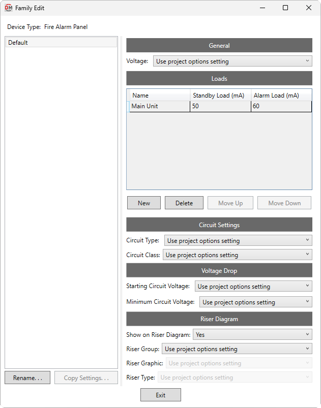
General
- Voltage: ▾ The voltage of the panel. This value is displayed in the voltage drop calculation schedule.
- Use project options setting The System voltage specified in the Project Options command will be used.
- Based on parameter The value for the specified parameter will be used. Press the button to select a parameter. Visit the Using Non-FireBIM Parameters for FireBIM Settings article in the knowledge base for more information.
- Custom Enter a voltage in the field provided.
Loads
This section defines the loads for the panel itself, as well as any internal components not shown on the Revit model, such as displays, interfaces, communication modules, or expanders.
Loads defined in this section cannot be modified on panel instances in the project. Loads can be defined on panel instances using the Panel Edit command. Quantities for family-level and instance-level loads are also set on panel instances.
-
Name The name of the component that will be displayed on the battery calculation schedule. Component names must be unique.
-
Standby Load The current draw in standby mode for one instance of the component.
-
Alarm Load The current draw in alarm mode for one instance of the component.
-
Adds a new row to the bottom of the list.
-
Deletes the selected row.
-
Moves the selected row up in the list.
-
Moves the selected row down in the list.
Circuit Settings
-
Circuit Type: ▾ The circuit type used by circuits connected to the panel. The values in this list are based upon the Circuit Types command.
- Use project options setting The Default circuit type ▾ specified in the Project Options command will be used.
- Custom Enter a circuit type in the field provided.
warningIf the specified circuit type does not exist in the project, the panel will use the project default.
-
Circuit Class: ▾ Whether circuits connected to the panel are class A or class B when calculating circuit length and voltage drop.
- Use project options setting The Default circuit class ▾ specified in the Project Options command will be used.
Voltage Drop
-
Starting Circuit Voltage: ▾ The starting voltage used when calculating voltage drop for the panel.
- Use project options setting The Starting circuit voltage specified in the Project Options command will be used.
- Based on parameter The value for the specified parameter will be used. Press the button to select a parameter. Visit the Using Non-FireBIM Parameters for FireBIM Settings article in the knowledge base for more information.
- Custom Enter a voltage in the field provided.
-
Minimum Circuit Voltage: ▾ The minimum voltage allowed on circuits connected to the panel. Circuits with devices that drop below this voltage will be upsized if able. Calculated voltages below this value will be highlighted in voltage drop schedules.
- Use project options setting The Minimum circuit voltage specified in the Project Options command will be used.
- Based on parameter The value for the specified parameter will be used. Press the button to select a parameter. Visit the Using Non-FireBIM Parameters for FireBIM Settings article in the knowledge base for more information.
- Custom Enter a voltage in the field provided.
Riser Diagram
-
Show on Riser Diagram: ▾ Whether the panel can be selected in the Panel Insert command. The default setting is Yes.
-
Riser Group: ▾ The graphic category used for the panel when it is inserted on the riser diagram. The groups available are based upon settings in the Riser Diagram Device Graphics command.
- Use project options setting The Default panel graphic group ▾ specified in the Project Options command will be used.
-
Riser Graphic: ▾ The default riser diagram graphic family used for the panel. The values in this list are based upon the Riser Diagram Device Graphics command and the selected Riser Group ▾.
-
Riser Type: ▾ The riser diagram graphic type used for the selected Riser Graphic ▾.