Circuit Edit

Allows you to set information used for sizing circuits and displaying circuits on the riser diagram.
Opens the Circuit Edit dialog box:
Circuit Edit Dialog Box
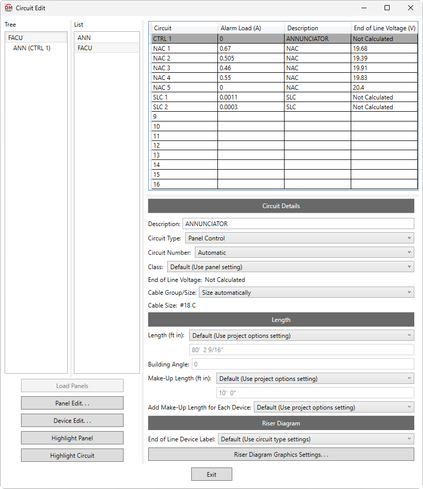
Panel Tree & List
-
Tree / List ☰ All of the fire alarm panels in your project. They are organized based upon the connections in the model, and listed alphabetically by device name.
You can select multiple panels in the tree and list using the SHIFT or CTRL key.
-
If you run the
Circuit Edit command with one or more panels or circuited devices selected, only the selected panels will appear in the Tree / List ☰. Press this button to display the rest of the fire alarm panels in the model. -
Press this button to close this dialog box and run the Panel Edit command with the selected panel active.
-
Press this button to close this dialog box and run the Device Edit command with the devices on the selected circuit active.
-
Press this button to highlight the selected panel in the model or on the riser diagram, similar to the Revit Highlight in Model command. If the device exists on multiple views, you will be prompted to specify a view.
-
Press this button to highlight all of the devices on the selected circuit in the model or on the riser diagram, similar to the Revit Highlight in Model command. If the devices exist on multiple views, you will be prompted to specify a view.
Circuit Table
This section lists all of the circuits on the selected panel. If multiple panels are selected, circuits for all of the panels will be listed. You can select multiple circuits using the SHIFT or CTRL key.
Information about the selected circuit is displayed below the circuit table. When an empty row is selected that has nothing connected to it, you will not be able to make any changes. When a circuit is selected, changes can be made to the circuit using the fields described in the sections below. If multiple circuits are selected, fields that have different values across the selected circuits will display <Varies>.
-
Circuit ☰ The circuit type and number for the circuit. Circuits are grouped based upon the Circuit Type ▾ and numbered based upon the Circuit Number ▾.
-
Description The description for the circuit as it will appear in schedules and annotation tags. Changes made to this field will be reflected in the Description field in the Circuit Details section of the dialog box.
Circuit Details
-
Description: The description for the circuit as it will appear in schedules and annotation tags.
-
Circuit Type: ▾ The circuit type used by the circuit. The values in this list are based upon the Circuit Types command.
- Default The circuit type is based upon the Circuit Type ▾ setting in the panel in the Panel Edit command.
-
Circuit Number: ▾ How the number is generated for the circuit.
- Automatic The number is generated automatically based upon the Revit circuit order and quantity of circuits with the same Circuit Type ▾ on the panel.
- Custom Enter a custom number in the field provided.
-
Class: ▾ Whether the circuit is considered class A or class B when assigning end-of-line graphics on the riser diagram, and when calculating circuit length and voltage drop.
- Default The class is based upon the Circuit Class ▾ setting in the panel in the Panel Edit command.
-
End of Line Voltage: The voltage at the last device on the circuit. This value is based upon the load on the circuit, the cable size, and the circuit length. If the Circuit Type ▾ used by the circuit is set to not calculate voltage drop, Not Calculated will be displayed.
-
Cable Group/Size: ▾ Sets the sizing method for the cable.
- Size automatically The cable is set to the Default Group ▾ and Default Size ▾ for the specified Type ▾. The cable may be upsized when needed to reduce voltage drop based upon the Upsize for Voltage Drop ▾ setting for the specified Type ▾.
- Cable size group The cable is set to the smallest size defined in the cable size group chosen from the list. The cable may be upsized when needed to reduce voltage drop based upon the Upsize for Voltage Drop ▾ setting for the specified Type ▾.
- Specific size The cable is set to the size chosen from the list.
-
Cable Size: Displays the current cable size.
Length
-
Length: ▾ How the length of the circuit is calculated. Except where noted, the length displayed includes length added by the Make-Up Length ▾ and Add Make-Up Length for Each Device ▾ settings, if any.
- Default The length is calculated based upon the Circuit Length Calculation Method ▾ setting in the panel in the Panel Edit command.
- Straight line The length is calculated based upon the straight line distance between the panel and the devices on the circuit, ending at the last device. This calculation approximates lengths for cables running directly between devices, typically underground or through the ceiling. If Class ▾ is set to A, the straight line distance from the last device back to the panel will also be included.
- Right angles The length is calculated based upon the distance along the axes of the building between the panel and the devices on the circuit, ending at the last device. This calculation approximates lengths for cables running along the walls of the building. If Class ▾ is set to A, the distance along the building axes from the last device back to the panel will also be included.
- Revit calculated length The length is based upon the distance that Revit calculates using the Circuit Path feature. The Make-Up Length ▾ and Add Make-Up Length for Each Device ▾ settings are ignored.
- Fixed Enter the length of the circuit in the field provided. The Make-Up Length ▾ and Add Make-Up Length for Each Device ▾ settings are ignored.
tipFor the Straight line and Right angles calculation methods, use the Revit Systems→Wire commands to draw wires between circuited devices on the plan view. FireBIM uses these wires to determine device ordering on the circuit, which will affect the length calculation. Visit Draw Wires for Circuits on Plan Views for more information.
-
Building Angle: The orientation of the building used when Circuit Length ▾ is set to Right angles. Visit the How Building Angle Affects Calculations article in the knowledge base for more information about this setting.
-
Make-Up Length: ▾ Additional length added to automatically calculated circuit lengths to represent make-up in the field.
- Default The length is based upon the Circuit Make-Up Length ▾ setting in the panel in the Panel Edit command.
- Custom Enter a custom length in the field provided.
-
Add Make-Up Length for Each Device: ▾ Whether the length specified in Make-Up Length ▾ is added for each device on the circuit.
- Default The setting is based upon the Add Circuit Make-Up Length for Each Device ▾ setting in the panel in the Panel Edit command.
- Yes The length is added for each device on the circuit. For point-to-point voltage drop calculations, the Make-Up Length ▾ will be added to the length to each device on the circuit.
- No The length is added once, regardless of the number of devices on the circuit. For point-to-point voltage drop calculations, the Make-Up Length ▾ will be added to the length to the first device on the circuit.
Riser Diagram
-
End of Line Device Label: The label used for the end-of-line device on the circuit, if any.
- Default The End of Line Device Label specified for the circuit type in the Circuit Types command will be used.
- Custom Enter a label in the field provided.
-
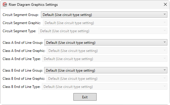
Press this button to open the Riser Diagram Graphics Settings dialog box. Use this dialog box to manage the graphics that represent the circuit on the riser diagram.
-
Circuit Segment Group: ▾ The graphic category inserted on the riser diagram for circuit segments between devices. The groups available are based upon settings in the Riser Diagram Wire Graphics command.
- Default The Segment Group specified for the circuit type in the Circuit Types command will be used.
-
Circuit Segment Graphic: ▾ The segment graphic used when the circuit is inserted on the riser diagram. The values in this list are based upon the Riser Diagram Wire Graphics command and the selected Circuit Segment Group ▾.
-
Circuit Segment Type: ▾ The graphic type used for the selected Circuit Segment Graphic ▾.
-
Class A End of Line Group: ▾ The graphic category inserted on the riser diagram after the last device on class A circuits. The groups available are based upon settings in the Riser Diagram Device Graphics command.
- Default The Class A End of Line Group ▾ specified for the circuit type in the Circuit Types command will be used.
- Use project options setting The Default class A end of line graphic group ▾ specified in the Project Options command will be used.
- None No end of line graphic will be inserted.
-
Class A End of Line Graphic: ▾ The default riser diagram graphic family inserted on the riser diagram after the last device on class A circuits. The values in this list are based upon the Riser Diagram Device Graphics command and the selected Class A End of Line Group ▾.
- Use project options setting The Default class A end of line graphic ▾ specified in the Project Options command will be used.
-
Class A End of Line Type: ▾ The riser diagram graphic type used for the selected Class A End of Line Graphic ▾.
-
Class B End of Line Group: ▾ The graphic category inserted on the riser diagram after the last device on class B circuits. The groups available are based upon settings in the Riser Diagram Device Graphics command.
- Default The Class B End of Line Group ▾ specified for the circuit type in the Circuit Types command will be used.
- Use project options setting The Default class B end of line graphic group ▾ specified in the Project Options command will be used.
- None No end of line graphic will be inserted.
-
Class B End of Line Graphic: ▾ The default riser diagram graphic family inserted on the riser diagram after the last device on class B circuits. The values in this list are based upon the Riser Diagram Device Graphics command and the selected Class B End of Line Group ▾.
- Use project options setting The Default class B end of line graphic ▾ specified in the Project Options command will be used.
-
Class B End of Line Type: ▾ The riser diagram graphic type used for the selected Class B End of Line Graphic ▾.
-