Panel Edit

Allows you to view and edit the information for panels in your project.
If you are in a drafting view, you will be prompted to specify a panel in the view or press ESC.
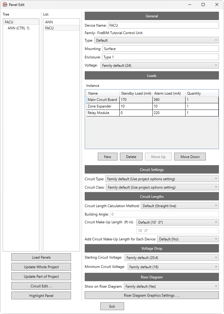
Opens the Panel Edit dialog box:
Panel Edit Dialog Box
-
Tree / List ☰ All of the fire alarm panels in your project. They are organized based upon the connections in the model, and listed alphabetically by Device Name.
You can select multiple panels in the tree and list using the SHIFT or CTRL key. Fields that have different values across the selected panels will display <Varies>.
-
If you run the
Panel Edit command with one or more panels selected, only the selected panels will appear in the Tree / List ☰. Press this button to display the rest of the panels in the model. -
Press this button to run the Update Whole Project command.
-
Press this button to run the Update Part of Project command beginning at the selected panel.
-
Press this button to close this dialog box and run the Circuit Edit command with the selected panel active.
-
Press this button to highlight the selected panel in the model or on the riser diagram, similar to the Revit Highlight in Model command. If the device exists on multiple views, you will be prompted to specify a view.
General
-
Device Name: The name of the panel. This is the same value as the Revit Panel Name parameter. Changing the Device Name in this dialog box will also change the Panel Name. It will also update the name of the panel schedule associated with this panel.
-
Family: The family of the panel. This value is read-only and cannot be changed in this dialog box.
-
Type: ▾ The family type of the panel. The types in the list are based upon the panel Family.
-
Mounting: How the device is mounted. This field is the same value as the Revit Mounting parameter that can be set in the General section of the Properties panel for the device.
-
Enclosure: The enclosure for the device. This field is the same value as the Revit Enclosure parameter that can be set in the General section of the Properties panel for the device.
-
Voltage: ▾ The voltage of the panel. This value is displayed in the voltage drop calculation schedule.
- Family default The Voltage ▾ specified in the panel family will be used.
- Use project options setting The System voltage specified in the Project Options command will be used.
- Based on parameter The value for the specified parameter will be used. Press the button to select a parameter. Visit the Using Non-FireBIM Parameters for FireBIM Settings article in the knowledge base for more information.
- Custom Enter a voltage in the field provided.
Loads
This section defines the loads for the panel itself, as well as any internal components not shown on the Revit model, such as displays, interfaces, communication modules, or expanders. This section will contain one or two tables of loads, depending upon whether the panel family has been configured using the Family Edit command: a Family table and an Instance table. In the Family table, only the Quantity can be modified in this dialog box.
-
Name The name of the component that will be displayed on the battery calculation schedule. Component names must be unique.
-
Standby Load The current draw in standby mode for the component.
-
Alarm Load The current draw in alarm mode for the component.
-
Quantity The quantity of the component. The Standby Load and Alarm Load will be multiplied by this value for calculations.
-
Adds a new row to the bottom of the list.
-
Deletes the selected row.
-
Moves the selected row up in the list.
-
Moves the selected row down in the list.
Circuit Settings
-
Circuit Type: ▾ The circuit type used by circuits connected to the panel. The values in this list are based upon the Circuit Types command.
- Family default The Circuit Type ▾ specified in the panel family will be used.
- Use project options setting The Default circuit type ▾ specified in the Project Options command will be used.
-
Circuit Class: ▾ Whether circuits connected to the panel are considered class A or class B when assigning end-of-line graphics on the riser diagram, and when calculating circuit length and voltage drop.
- Family default The Circuit Class ▾ specified in the panel family will be used.
- Use project options setting The Default circuit class ▾ specified in the Project Options command will be used.
Circuit Lengths
The fields in this section set how lengths are calculated for circuits connected to the panel. Visit the Length section of the Circuit Edit command for more information.
Voltage Drop
-
Starting Circuit Voltage: ▾ The starting voltage used when calculating voltage drop for the panel.
- Family default The Starting Circuit Voltage ▾ specified in the panel family will be used.
- Use project options setting The Starting circuit voltage specified in the Project Options command will be used.
- Based on parameter The value for the specified parameter will be used. Press the button to select a parameter. Visit the Using Non-FireBIM Parameters for FireBIM Settings article in the knowledge base for more information.
- Custom Enter a voltage in the field provided.
-
Minimum Circuit Voltage: ▾ The minimum voltage allowed on circuits connected to the panel. Circuits with devices that drop below this voltage will be upsized if able. Calculated voltages below this value will be highlighted in voltage drop schedules.
- Family default The Minimum Circuit Voltage ▾ specified in the panel family will be used.
- Use project options setting The Minimum circuit voltage specified in the Project Options command will be used.
- Based on parameter The value for the specified parameter will be used. Press the button to select a parameter. Visit the Using Non-FireBIM Parameters for FireBIM Settings article in the knowledge base for more information.
- Custom Enter a voltage in the field provided.
Riser Diagram
-
Show on Riser Diagram: ▾ Whether the panel can be selected in the Panel Insert command. The default setting is Yes.
-
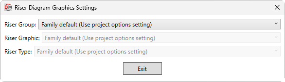
Press this button to open the Riser Diagram Graphics Settings dialog box. Use this dialog box to manage the graphics that represent the panel on the riser diagram.
-
Riser Group: ▾ The graphic category used for the panel when it is inserted on the riser diagram. The groups available are based upon settings in the Riser Diagram Device Graphics command.
- Family default The Riser Group ▾ specified in the panel family will be used.
- Use project options setting The Default panel graphic group ▾ specified in the Project Options command will be used.
-
Riser Graphic: ▾ The default riser diagram graphic family used for the panel. The values in this list are based upon the Riser Diagram Device Graphics command and the selected Riser Group ▾.
- Family default The Riser Graphic ▾ specified in the panel family will be used.
- Use project options setting The Default panel graphic ▾ specified in the Project Options command will be used.
-
Riser Type: ▾ The riser diagram graphic type used for the selected Riser Graphic ▾.
-
System voltage: The displayed voltage of the fire alarm system.
Default values for settings in the Circuit Settings and Circuit Lengths sections can be viewed and modified in the Circuits Project Options section.
Default values for settings in the Voltage Drop section can be viewed and modified in the Voltage Drop Project Options section.
Default values for settings in the Riser Diagram section can be viewed and modified in the Riser Diagram Project Options section.