Insert Connection Point

Allows you to add circuit connection points to your riser diagram graphic families. These connection points are used as snap points when circuits are drawn automatically.
You will be prompted to specify whether the graphic is for fire alarm panels or devices. For panel graphics, you will also be prompted to specify whether you want to insert an upstream or downstream connection. The different connection point types are detailed below.
You will then be prompted to specify the location of the connection point.
Click to place a free instance (Space Bar to Rotate)
The connection point will be inserted.
When customizing your riser diagram graphic families, you can assign dimensions to a parameter, which will allow you to resize the graphic after it has been inserted. The connection points can be constrained in the family such that they move during resizing.
For FireBIM to recognize when this resizing occurs and connect circuits to the correct points, parameters used for resizing must be assigned to the Graphics or Dimensions groups in Revit. You can specify the parameter group in the Revit Parameter Properties dialog box using the Group parameter under: ▾ setting.
Panel Connection Points
For panel graphic connection points, when the connection point is first inserted, Upstream connection points will lead out of the top of the graphic. Downstream connection points will lead out of the bottom of the graphic and offset to both sides.
To change whether the connection point is upstream or downstream and which direction circuits should extend, select the connection point and use the Type Selector ▾ in the Revit Properties panel:
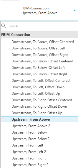
Each connection point type is differentiated by whether it is upstream or downstream, the direction of the circuit connection, and the direction in which additional circuits are offset.
Downstream / Upstream
-
Upstream Displayed in the family as arrows with IN text. The circuit to the upstream panel will connect to this point.
-
Upstream 2 Displayed in the family as arrows with IN2 text. Used for the secondary source of a panel with two circuits, such as an auxiliary source.
-
Downstream, Circuit Displayed in the family as arrows with OUT text. The first circuit to a downstream panel or device will connect to this point. Additional circuits will be offset from this point as described in the Offset section.
Above / Below / Left / Right
The direction of the arrow displayed for the connection point indicates how circuits will connect to and from the panel.
Rotating or mirroring the connection point will not change how circuits connect to it. To change the direction, you must select a different type.
-
To Above / From Above Circuits will connect to the top.
-
To Below / From Below Circuits will connect to the bottom.
-
To Left / From Left Circuits will connect to the left.
-
To Right / From Right Circuits will connect to the right.
Offset
-
Offset Left / Offset Right / Offset Down / Offset Up Additional circuits will be offset in the direction specified.
-
To Above, Offset Centered / To Below, Offset Centered Additional circuits will alternate being offset to the right and to the left of the connection point.
-
To Left, Offset Centered / To Right, Offset Centered Additional circuits will alternate being offset below and above the connection point.
Device Connection Points
For device graphic connection points, the connection directions are not specified. When circuits are drawn from the device graphic to the panel or to other devices on the circuit, the closest connection point will be used.