Performing Voltage Drop Calculations
Create a voltage drop calculation schedule and make changes to affect the results.
Start in the CALCULATION SCHEDULES drafting view.
Create the Voltage Drop Schedule
-
Run the
FireBIM Design→ command. The Select Panel for Voltage Drop Calculation dialog box will open. Voltage Drop Schedule
 -
Select FACU from the list and press the button. The Insert Voltage Drop Calculation Schedule dialog box will open.
-
Press the button to close the dialog box.
-
Follow the prompts to insert the voltage drop calculation schedule on the drafting view.
Modify Calculated Circuits & Update the Schedule
If you already made changes to circuits while following the Setting Circuit Types section of the tutorial, those circuits will not appear in the voltage drop schedule. Otherwise, follow the steps below to exclude specific circuits from the calculation.
-
Run the
FireBIM Design→ command. The Circuit Edit dialog box will open. Circuit Edit
 -
Select circuits NAC 6 and NAC 7 using the circuit table. You can use the CTRL or SHIFT keys to select multiple circuits.
-
Set Circuit Type ▾ to SLC. The circuits will be renamed SLC 1 and SLC 2, and NAC 8 will be renamed NAC 6.
-
Select circuit NAC 6 using the circuit table.
-
Set Circuit Type ▾ to Panel Control. The circuit will be renamed CTRL 1.
-
Press the button to close the dialog box.
-
Run the
FireBIM Design→ command. Schedule Update
 -
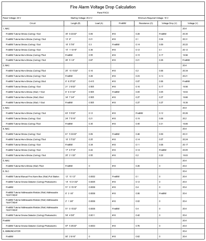
Select the voltage drop calculation schedule on the drafting view. The schedule will update to exclude the modified circuits.
Using the default customization, only NAC circuits will be included in voltage drop schedules. This behavior can be modified using the ![]() Customization→ Circuit Types
Customization→ Circuit Types
Make Changes & Update the Schedule
-
Open the SECOND FLOOR FP CEILING plan view.
-
Run the Revit Systems→Device→
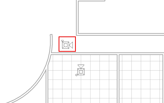
 Fire Alarm command and insert a ceiling-mounted horn/strobe in the south hallway, as shown in the image below.note
If you already added the horn/strobe while following the Adding & Removing Devices section of the riser diagram tutorial, you can erase the horn/strobe instead. If you do, skip to step 6.
-
Select the horn/strobe in the south-facing room and run the Revit Electrical Circuits→
 Edit Circuit command.
 -
Select the horn/strobe in the south hallway to add it to the circuit.
-
Run the Revit Edit Circuit→
 Finish Editing Circuit command to save your changes.
-
Select a strobe in one of the north-facing rooms and run the
FireBIM Design→ command. The Circuit Edit dialog box will open with circuit NAC 4, the circuit for the selected device, active. Circuit Edit -
In the Circuit Details section, set Add Make-Up Length for Each Device ▾ to Yes.
-
Set Make-Up Length ▾ to Custom and enter 200 in the field provided.
The End of Line Voltage values will update.
The Cable Size value will update to #16 to indicate it has been automatically upsized to reduce voltage drop. -
Press the button to close the dialog box.
-
Return to the CALCULATION SCHEDULES drafting view.
-
Run the
FireBIM Design→ command. Schedule Update -
Select the voltage drop calculation schedule on the drafting view. The schedule will update to show the new device on circuit NAC 3, and the new values on circuit NAC 4.
-
Run the
FireBIM Design→ command. The Circuit Edit dialog box will open. Circuit Edit -
Select circuit NAC 4 using the circuit table.
-
In the Circuit Details section, set Cable Group/Size ▾ to #18 Uncoated.
The End of Line Voltage values will update. -
Press the button to close the dialog box.
-
Run the
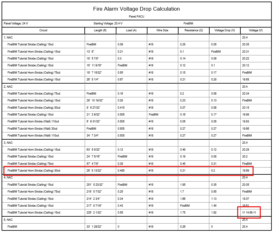
FireBIM Design→ command and select the voltage drop calculation schedule on the drafting view. The schedule will update to show the new values. Voltages below 16V will be highlighted. Schedule Update
You may notice the updated voltage drop calculations put the newly inserted horn/strobe at the end of circuit 3, which can affect how the circuit length and point-to-point loads are calculated. This occurs when wires drawn on the plan view do not reflect how the devices are circuited. Visit Draw Wires for Circuits on Plan Views for more information.