Adding & Removing Devices
Add, remove, and rearrange circuited devices on the plan view and riser diagram.
Start in the SECOND FLOOR FP CEILING plan view.
Add & Remove Devices on a Circuit
-
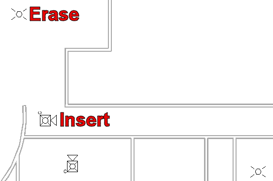
Run the Revit Systems→Device→
 Fire Alarm command and insert a ceiling-mounted horn/strobe in the south hallway, as shown in the image below.
 -
Select the horn/strobe in the south-facing room and run the Revit Electrical Circuits→
 Edit Circuit command.
 -
Select the horn/strobe in the south hallway to add it to the circuit.
-
Run the Revit Edit Circuit→
 Finish Editing Circuit command to save your changes.
 -
Erase the strobe located in the lobby near the newly inserted horn/strobe, shown in the image below.
-
Open the RISER DIAGRAM drafting view.
-
Run the
FireBIM Riser→ command. Circuit Update
 -
Select an element on circuit 3. The circuit will update in place to show the changes.
Modify Device Ordering on a Circuit
When updating circuit 3, the order of the devices on the circuit will change. This can occur when wires drawn on the plan view do not reflect how the devices are circuited. Visit Draw Wires for Circuits on Plan Views for more information. Follow the steps below to modify how the devices are ordered on the circuit.
-
Open the SECOND FLOOR FP plan view.
-
Erase the wires that previously led to the strobe in the lobby.
-
Run one of the Revit Systems→Wire commands, such as
 Chamfered Wire.
 -
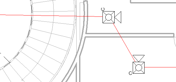
Hover your cursor over the remaining strobe in the lobby until it snaps to a Point, then select that point to start drawing a wire.
infoThe Point corresponds to the electrical connector on the device. Drawn wires must connect to these Points to be associated with the circuit.
-
Hover over the newly inserted horn/strobe until it snaps to a Point, then select that point to insert a wire segment connecting the two devices.
-
Repeat steps 4 and 5 to draw a wire connecting the newly inserted horn/strobe to the other horn/strobe on the circuit.
-
Press ESC to exit the command.
-
Open the RISER DIAGRAM drafting view.
-
Run the
FireBIM Riser→ command. Circuit Update -
Select an element on circuit 3. The circuit will update in place to show the changes.
