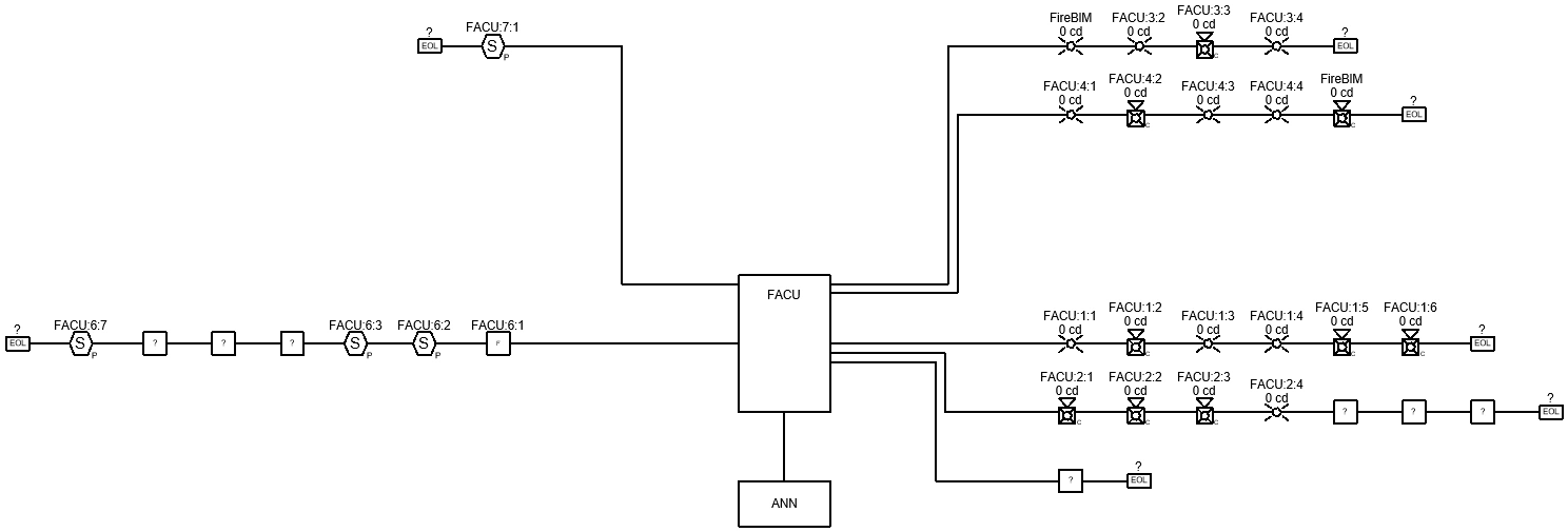
Inserting Circuits
Insert circuits and devices connected to the control unit onto the riser diagram.
Start in the RISER DIAGRAM drafting view.
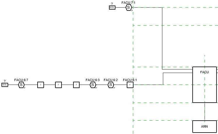
Before inserting circuits, you can draw Revit detail lines (keyboard shortcut DL) on the drafting view to line up your insertion points.
The instructions in this section have been updated to reflect the latest FireBIM functionality. Videos and screenshots will be updated closer to the official release of FireBIM 1.0.
Insert Circuits 7 & 6
-
Run the
FireBIM Riser→ command. Circuit Insert
 -
Select the control unit on the drafting view. The Insert Circuit dialog box will open.
-
Select circuit 7 from the list and press the button to close the dialog box.
-
Specify an insertion point above and to the left of the control unit on the drafting view.
-
Specify a point further to the left of the insertion point; the circuit will wrap at that point if needed. The devices on circuit 7 will be inserted on the drafting view.
-
Repeat steps 1 through 4 to insert circuit 6 directly to the left of the control unit. Circuit 6 will have the same vertical alignment and wrap point as circuit 7. Devices on the circuit will follow the order in which the circuit wires are drawn in the FIRST FLOOR FP plan view.
Insert Circuits 3 & 4
-
Select the control unit on the drafting view and run the
FireBIM Riser→ command. The Insert Circuit dialog box will open with the control unit selected. Circuit Insert -
Select circuits 3 and 4 from the list by holding CTRL or SHIFT while selecting, then press the button to close the dialog box.
-
Specify an insertion point above and to the right of the control unit on the drafting view.
-
Specify a point further to the right of the insertion point; the circuit will wrap at that point if needed. Circuits 3 and 4 will be inserted on the drafting view.
Insert the Remaining Circuits
-
Select the control unit on the drafting view and run the
FireBIM Riser→ command. The Insert Circuit dialog box will open with the control unit selected. Circuit Insert -
Select circuits 1, 2, and 5 from the list by holding CTRL while selecting, then press the button to close the dialog box.
-
Specify an insertion point directly to the right of the control unit on the drafting view. Circuits 1, 2, and 5 will be inserted on the drafting view, using the same vertical alignment and wrap point as circuits 3 and 4.
Because the graphics for the modules and wall-mounted horn/strobes were not configured in the family or instance, they will insert with placeholder graphics. The default graphic used for placeholders can be changed in the Riser Diagram: Devices section of the
While not necessary for these tutorials, you can use the commands available on the Wires panel of the FireBIM Riser ribbon to adjust how the circuits are routed after insertion on the riser diagram.