Setting Circuit Types
View and modify circuit types defined in the project, then assign circuit types to specific circuits.
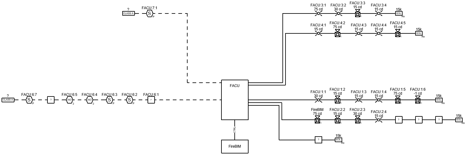
Start in the RISER DIAGRAM drafting view.
-
Run the
FireBIM Design→ command. The Circuit Types dialog box will open. Customization→ Circuit Types
 -
Select the NAC circuit type and make the following changes:
- Set Class B End of Line Graphic ▾ to Resistor.
- Set End of Line Device Label to 15k.
-
Select the Panel Control circuit type and make the following changes:
- Set Segment Group ▾ to Segment.
- Set Segment Graphic ▾ to Segment Text.
- Set Segment Type ▾ to New Solid.
-
Select the SLC circuit type from the list and make the following changes:
- Set Segment Group ▾ to Segment.
- Set Segment Graphic ▾ to Segment Simple.
- Set Segment Type ▾ to New Dashed.
-
Press the button to save your changes and close the dialog box.
-
Run the
FireBIM Design→ command. The Circuit Edit dialog box will open. Circuit Edit
 -
Select circuits NAC 6 and NAC 7 using the circuit table. You can use the CTRL or SHIFT keys to select multiple circuits.
-
Set Circuit Type ▾ to SLC. The circuits will be renamed SLC 1 and SLC 2, and NAC 8 will be renamed NAC 6.
-
Set Class ▾ to A.
-
Select circuit NAC 6 using the circuit table.
-
Set Circuit Type ▾ to Panel Control. The circuit will be renamed CTRL 1.
-
Press the button to close the dialog box. The graphics for the modified circuits will be updated.
Update the Riser Diagram
While the specific devices and circuits modified showed their changes immediately, some graphics have not been updated. To update all of the values, graphics, and labels in the project, run the ![]() Update Whole Project
Update Whole Project