Circuiting
The
To manage the circuits on your distribution equipment, go to
Ribbon: ![]() Circuiting
Circuiting
Pulldown Menu:
Circuiting Dialog Box
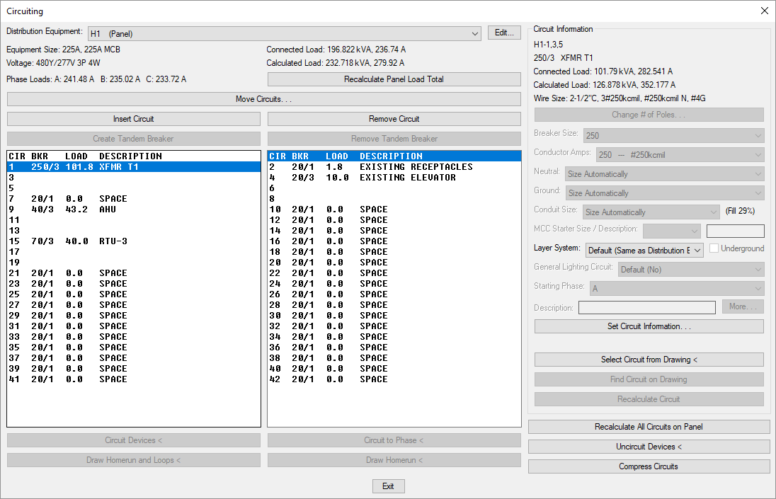
The Circuiting dialog box is divided into two main sections. The left section displays information about and circuits associated with the active distribution equipment. Select the circuit you want to configure from the list. The Circuit Information section on the right allows you to modify the selected circuit.
-
Distribution Equipment: ▾ The active distribution equipment. The circuits listed are associated with the distribution equipment displayed. Changing the equipment will display new circuits in the circuit lists.
Information about the active distribution equipment is displayed below this field. The size, voltage, total connected and calculated load in kVA, and connected load in amps on each phase are all displayed.
-
Press this button to recalculate the load total on the active distribution equipment. The total connected and calculated load in kVA and connected load in amps on each phase will be updated to match the current loads connected to the equipment and any distribution equipment connected to it.
-
Press this button to open the Move Circuits dialog box with the currently selected circuit active. Visit the Move Circuits section for more information.
-
Press this button to insert a new circuit in the active distribution equipment. A single-pole circuit will be inserted in the circuit list at the location of the active circuit. The active circuit and all of the circuits below it will be shifted down.
If there are no spaces available below the active circuit, no circuit will be inserted.
-
Press this button to remove an unused circuit from the active distribution equipment. All of the circuits below the selected circuit will be shifted up in the circuit list. A new unused circuit will be inserted at the bottom of the circuit list. This button cannot be used if the circuit has any devices connected to it or any fixed loads set in it.
-
Press this button to convert the selected circuit to a tandem breaker.
-
Press this button to convert a tandem breaker to a circuit.
-
Circuit Lists ☰ There are two lists of circuits in the Circuiting dialog box. Panels will display odd circuits in the list on the left and even circuits in the list on the right. All other distribution equipment types will display their circuits in the list on the left. Only one circuit in the two lists can be selected at a time. Actions taken in the rest of the dialog box will affect the selected circuit.
-
Press this button to connect devices on the drawing to the currently selected circuit. Visit the Circuit Devices section for more information.
-
Press this button to connect devices on the drawing to a specific phase of the currently selected circuit. Visit the Circuit to Phase section for more information.
-
Press this button to draw a homerun and loops on devices on the drawing. Visit the Draw Homerun and Loops section for more information.
-
Press this button to draw a homerun on a device on the drawing. Visit the Draw Homerun Only section for more information.
Circuit Devices
Press the button to connect devices on the drawing to a circuit on a distribution equipment.
If a device is already connected to a circuit, the button can be used to remove it from the previous circuit and connect it to a new circuit in one action. Using the button is not needed.
The Circuiting dialog box will close. The circuit that was selected in the Circuit List ☰ starts as the current circuit. The current circuit can be changed during the command by incrementing the circuit, explained below.
You will be prompted to select the devices to be circuited. The current circuit, the load connected to the circuit, the size of the breaker on the circuit, and the starting phase of the circuit are all listed on the command line.
Select devices to be circuited:
Current Circuit: <Circuit> Connected KVA: <Load> Breaker Amps: <Breaker Size> Phase: <Phase Letter>
Press ENTER once to increment the circuit, twice to return to circuiting dialog.
-
Select deviceSelect one or more devices to be connected to the current circuit. The devices will be connected if the voltage matches the circuit.A circuit label listing the panel and circuit number will be inserted next to the selected devices. The circuit label will be updated or removed when the homerun and loops are drawn for the circuit.
If you select a device with multiple loads, you will be prompted to specify which loads you want to connect to the current circuit.
If the circuit is a space and the device has more poles than the circuit, the software will attempt to join together circuits below the current circuit to make a circuit large enough for the device. If the circuits below are not spaces, they cannot be joined with the current circuit. The device will not be connected to the current circuit.
If the circuit is a space and the device has fewer poles than the circuit, the circuit will be split into multiple single-pole circuits. The device will be connected to the first circuit. The other circuits will be left as single-pole spaces in the distribution equipment.
-
Increment circuitPress ENTER once to increment to the next circuit. On panels, the next circuit will be on the same side of the panel as the current circuit. The increment function will not move between the odd and even sides of the panel. -
Return to circuiting dialogPress ENTER twice without circuiting a device to return to the Circuiting dialog box.
Circuit to Phase
Press the button to connect devices on the drawing to a specific phase of a circuit on a distribution equipment. There are two common uses for this button:
- Shared neutrals on multiwire branch circuits: NEC 2008 210.4b requires multiwire branch circuits that share a neutral to have the breakers all trip at the same time. Using this button, you can connect single-pole devices to a specific phase of a two-pole or three-pole circuit. All of the devices on the circuit will share a common neutral and have a common trip.
- 208V and 480V site lighting on three-phase circuits: It is common to connect two-pole site lights to three-pole circuits, rotating the phases that are connected to keep the load balanced. Using this button, you can connect two-pole light fixtures to specific phases of a three-pole circuit.
The Circuiting dialog box will close. The circuit that was selected in the Circuit List ☰ starts as the current circuit. The current circuit can be changed during the command by incrementing the circuit, explained below.
The Select Circuit Phase dialog box will open. You are prompted to select the phase of the circuit to which devices will be connected.

After you select the phase, you will be prompted to select the devices to be circuited. The current circuit, the load connected to the circuit, the size of the breaker on the circuit, and the starting phase of the circuit are all listed on the command line.
Select devices to be circuited:
Current Circuit: <Circuit> Connected KVA: <Load> Breaker Amps: <Breaker Size> Phase: <Phase Letter>
Press <Key>ENTER</Key> for circuiting options, twice to return to circuiting dialog.
-
Select deviceSelect the devices to be connected to the selected phase on the current circuit. The devices will be connected if the voltage matches the circuit.A circuit label listing the panel and circuit number will be inserted next to the selected devices. The circuit label will be updated or removed when the homerun and loops are drawn for the circuit.
If you select a device with multiple loads, you will be prompted to specify which loads you want to connect to the current circuit.
If the circuit is a space and the device has more poles than the circuit, the software will attempt to join together circuits below the current circuit to make a circuit large enough for the device. If the circuits below are not spaces, they cannot be joined with the current circuit. The device will not be connected to the current circuit.
If the device has fewer poles than the circuit, the device is connected to the selected phase on the current circuit. The number of poles on the circuit is not changed.
-
Circuiting optionsPress ENTER once to change the current phase or circuit.[Set phase/Increment circuit/<Return to circuiting dialog>]:-
Set phaseType S to select a new phase using the Select Circuit Phase dialog box, shown above. -
Increment circuitType I to increment to the next circuit. On panels, the next circuit will be on the same side of the panel as the current circuit. The increment function will not move between the odd and even sides of the panel. -
Return to circuiting dialogPress ENTER a second time or type R to return to the Circuiting dialog box.
-
Circuit Information
-
Circuit Information Displays information about the selected circuit, including the circuit callout, circuit description, connected and calculated loads in kVA and amps, and the size of the wire.
-
Press this button to change the number of poles for the selected circuit. Visit the Change Number of Poles section for more information.
-
Breaker Size: ▾ The size of the breaker for the selected circuit. The list of breaker sizes available can be customized. Visit the Wire Sizing section for more information.
- Size Automatically The breaker size is chosen automatically based upon the load connected to the circuit. The size is based upon 125% of the continuous load, and 100% or 125% of the noncontinuous load, depending upon the setting of the Size breakers to 100% of noncontinuous load ▾ option. Visit the Circuits, Load Types, and Wire Sizes options section for more information.
- None The circuit does not have a breaker. The breaker column in the distribution equipment schedule will display a slash and the number of poles (/1 or /2 or /3). No breaker size will be displayed.
- Specific size The selected breaker size is used for the circuit.
-
Conductor Amps: ▾ Sets the size of the hot wires for the selected circuit.
- Size Automatically The hot wires are sized based upon the Breaker Size ▾ field.
- None The circuit does not have a conductor wire. The wire callout for the circuit will be blank.
- Specific breaker and wire size The hot wires are sized to match the breaker and wire size chosen from the list.
-
Neutral: ▾ Sets the size of the neutral wire for the selected circuit. If the distribution equipment does not have a neutral, this field is disabled and set to None.
- Size Automatically The neutral wire is the same size as the hot wires as specified in the Conductor Amps ▾ field.
- None No neutral wire is included in the circuit. If the devices on the circuit require a neutral wire, this option is not available.
- Specific wire size The neutral wire is sized to match the wire size chosen from the list.
-
Ground: ▾ The size of the ground wire for the selected circuit.
- Size Automatically The ground wire is sized based upon the Equipment Ground ▾ setting for the larger of the two breaker sizes specified in the Breaker Size ▾ and Conductor Amps ▾ fields. The ground wire will never size automatically to be larger than the hot wires.
- None No ground wire is included in the circuit.
- Specific wire size The ground wire is sized to match the wire size chosen from the list.
-
Conduit Size: ▾ The size of the conduit for the selected circuit. The conduit fill percentage is displayed next to the Conduit Size ▾ field. Changing the conduit size will update the fill percentage.
- Size Automatically The conduit is sized automatically based upon the wires in the circuit. All conduits are sized using a 40% conduit fill per NEC Table 1.
- None No conduit is included for the circuit.
- Specific conduit size The conduit is sized to match the conduit size chosen from the list.
-
MCC Starter Size: ▾ The motor control center starter size. The value is displayed in the motor control center schedule. Applies only to motor control centers.
-
MCC Description: ▾ The motor control center description. The value is displayed in the motor control center schedule. Applies only to motor control centers.
-
Layer System: ▾ The layer system of the selected circuit. This layer system controls the layer that is used for the circuit callouts, homerun, and loops on the plan. If the selected circuit is shown on the one-line diagram, this layer system will also control the layer of the connected feeder. Visit the Layer System section for more information.
- Default The circuit will use the default circuit layer system. You can change the default layer system using the Default circuit layer system ▾ setting in the Circuits, Load Types, and Wire Sizes options section.
- <Layer System> The circuit will use the selected layer system.
-
☐ Underground Whether the circuit is underground.
Different layers are used for aboveground and underground loops. The default layers for underground loops use a dashed linetype. The layers can be changed using the Layers commands.
-
General Lighting Circuit: ▾ Whether the circuit is considered a general lighting circuit during load calculations. General lighting circuits are ignored when calculating loads.
-
Starting Phase: ▾ Sets the starting phase of the circuit. This value can be used on single-pole and two-pole circuits to balance the loads on distribution equipment.
This field is disabled for panels. The starting phase for each circuit on a panel is fixed.
-
Description: An additional description for the circuit that is shown on the distribution equipment schedule. This value is added before any other descriptions on the circuit from connected devices. To change the description on the circuit from the devices, change the device definition.
Press the button to open the More Circuit Description Settings dialog box. The following fields will be available for each phase:
-
Circuit Description Prefix: Text that is added before the circuit description.
-
Circuit Description Suffix: Text that is added after the circuit description.
-
Circuit Description Replacement: Text that overrides the circuit description. This value will also override the Circuit Description Prefix and Circuit Description Suffix.
-
-
Visit the Set Circuit Information section for more information.
-
Press this button to select a circuit based upon a device on the drawing. The dialog box will close and you will be prompted to select a device.
Select device on circuit to make current:After you select a device, the Circuiting dialog box will reopen with the circuit the selected device is connected to active.
-
Press this button to locate devices on the selected circuit. If there are any on the current drawing, the dialog box will close and they will be highlighted. If there are devices on another drawing but not the current drawing, you will have the option to open the other drawing. This button cannot be used on circuits that do not have any devices connected to them.
-
Press this button to recalculate the selected circuit. The load on the circuit will be recalculated based upon the connected devices. The breaker and wire sizes, if they are set to Size Automatically, will be recalculated based upon the newly calculated load.
-
Press this button to recalculate all of the circuits on the active distribution equipment. The loads on the circuits will be recalculated based upon the connected devices. The breaker and wire sizes, if they are set to Size Automatically, will be recalculated based upon the newly calculated loads.
-
Press this button to disconnect devices on the drawing from the circuit they are connected to. Visit the Uncircuit Devices section for more information.
-
Press this button to move all of the spaces in the distribution equipment to the bottom of the circuit lists. The order of the circuits with loads on them will be the same. Any unused circuits between circuits with loads will be moved.
Change Number of Poles
Press the button to change the number of poles for a selected circuit.
To comply with NEC 2008 210.4b, this button can be used to merge three single-pole circuits into one three-pole circuit. If there are devices on the single-pole circuits, they will remain on the corresponding phases of the three-pole circuit. The circuits will share a common neutral and a common trip.
The Change Number of Poles dialog box will open.

-
Circuit: The selected circuit.
-
🔘 Number of Poles Select the number of poles for the circuit. Options that are not allowed for the current circuit will be disabled.
Set Circuit Information
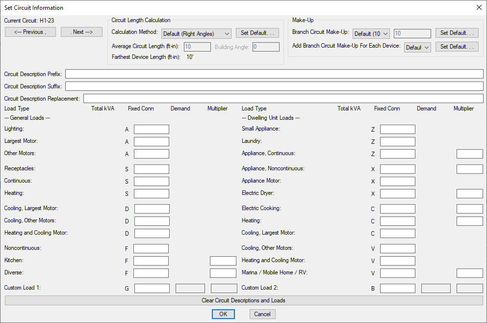
When you press the button, the Set Circuit Information dialog box will open.
-
Current Circuit: The selected circuit. Use the and buttons to select a different circuit.
-
Circuit Description Prefix: Text that is added before the circuit description.
-
Circuit Description Suffix: Text that is added after the circuit description.
-
Circuit Description Replacement: Text that overrides the circuit description. This value will also override the Circuit Description Prefix and Circuit Description Suffix.
Circuit Length Calculation
-
Calculation Method: ▾ How the circuit length is calculated. The values you can set vary depending upon the setting of this field.
- Default The default calculation method for the project. The default Circuit length calculation method ▾ setting can be changed in the Distribution Equipment Options section.
- Right Angles Calculate the circuit length using line segments at right angles to one another. The direction of the segments is determined by the Building Angle.
- Straight Line Calculate the circuit length using a straight line.
- Custom Set the circuit length manually.
-
Average Circuit Length: The calculated average length of the circuit to each device in feet and inches. This can be set manually when Calculation Method ▾ is set to Custom.
-
Building Angle: Sets the building angle relative to the alignment point when Calculation Method ▾ is set to Right Angles. The default Building angle setting can be changed in the Distribution Equipment Options section. Visit the How Building Angle Affects Calculations article in the knowledge base for more information about this setting.
-
Farthest Device Length: The length of the circuit to the farthest device in feet and inches.
Make-Up
-
Branch Circuit Make-Up: ▾ The extra length of wire included in branch circuit lengths to account for branch circuit connections. It is used in the fault calculation, voltage drop calculation, and takeoffs.
- Default The default make-up length for circuits on the distribution equipment. This value can be changed in the Schedule and Length Settings dialog box for the distribution equipment.
- Custom Set the make-up length manually.
-
Add Branch Circuit Make-Up For Each Device: ▾ Whether the length specified in Branch Circuit Make-Up ▾ is added for each device on the circuit.
- Default The default setting for circuits on the distribution equipment. This setting can be changed in the Schedule and Length Settings dialog box for the distribution equipment.
- Yes The make-up added to the branch circuit length is multiplied for each device on the circuit.
- No The make-up is only added to the branch circuit length once, regardless of the number of devices on the circuit.
Fixed Loads
Fixed loads are loads on a circuit that are not associated with a device on a drawing and must be specified manually. Loads are input in kVA. Existing loads are often modeled using fixed loads. Fixed load values are added to the load of any devices connected to the circuit.
Visit the Electrical Load Type Explanations article on the knowledge base for more information about each load type and when it should be used. Visit the Inserting Fixed Loads Using Keyboard Shortcuts article in the knowledge base for keyboard shortcuts available for entering fixed loads.
-
Lighting: Sets the fixed lighting load on the circuit.
-
Largest Motor: Sets the fixed largest motor load on the circuit. If a circuit has multiple motors connected to it, specify the load of the largest motor here. This will not necessarily be the largest motor on the distribution equipment or in the project. When the load on a distribution equipment is calculated, the largest of all of the largest motor loads will be used as the largest motor on the distribution equipment.
-
Other Motors: Sets the fixed other motor loads on the circuit. This load can represent multiple motors. The total can be larger than the largest motor. If a largest motor load is included on the circuit, this value will always be added to the other motors load for all of the distribution equipment it is connected to. If no largest motor load is included on the circuit, this value is treated as the largest motor load.
-
Receptacles: Sets the fixed non-dwelling receptacle load on the circuit.
-
Continuous: Sets the continuous load on the circuit.
-
Heating: Sets the fixed space-heating load on the circuit.
-
Cooling, Largest Motor: Sets the fixed load for the largest motor used for cooling on the circuit. If a circuit has multiple motors connected to it, specify the load of the largest motor here. This will not necessarily be the largest motor on the distribution equipment or in the project. When the load on a distribution equipment is calculated, the largest of all of the largest motor loads will be used as the largest motor on the distribution equipment.
-
Cooling, Other Motors: Sets the fixed loads for other motors used for cooling on the circuit. This load can represent multiple motors. The total can be larger than the largest motor. If a largest motor load is included on the circuit, this value will always be added to the other motors load for all of the distribution equipment it is connected to. If no largest motor load is included on the circuit, this value is treated as the largest motor load.
-
Heating and Cooling Motor: Sets the fixed heating and cooling motor load on the circuit.
-
Noncontinuous: Sets the noncontinuous load on the circuit.
-
Kitchen: Sets the fixed kitchen load on the circuit.
-
Kitchen (Multiplier): Sets the number of pieces of kitchen equipment on the circuit. The kitchen demand factor in NEC Table 120.56 is based upon the number of pieces of kitchen equipment.
-
Diversified: Sets the fixed diversified load on the circuit.
-
Diversified (Multiplier): Sets the multiplier for the calculated load of the diversified load.
-
Custom Load 1: Sets the fixed connected load for Custom Load Type 1 on the circuit. The label on the dialog box will match the Custom Load Type 1 Name option. Visit the Circuits, Load Types, and Wire Sizes options section for more information.
-
Custom Load 1 (Demand): Sets the fixed calculated load for Custom Load Type 1 on the circuit. This field is enabled if the Custom Load Type 1 Calculation method ▾ option is set to Variable calculated load.
-
Custom Load 1 (Multiplier): Sets the demand factor used to calculate the calculated load for Custom Load Type 1 on the circuit. This field is enabled if the Custom Load Type 1 Calculation method ▾ option is set to Variable calculated load.
-
Custom Load 2: Sets the fixed load for Custom Load Type 2 on the circuit. The label on the dialog box will match the Custom Load Type 2 Name option. Visit the Circuits, Load Types, and Wire Sizes options section for more information.
-
Custom Load 2 (Demand): Sets the fixed calculated load for Custom Load Type 2 on the circuit. This field is enabled if the Custom Load Type 2 Calculation method ▾ option is set to Variable calculated load.
-
Custom Load 2 (Multiplier): Sets the demand factor used to calculate the calculated load for Custom Load Type 2 on the circuit. This field is enabled if the Custom Load Type 2 Calculation method ▾ option is set to Variable calculated load.
-
Small Appliance: Sets the fixed small appliance load on the circuit.
-
Laundry: Sets the fixed laundry load on the circuit.
-
Appliance, Continuous: Sets the continuous load for appliances fastened in place on the circuit.
-
Appliance, Continuous (Multiplier): Sets the number of continuous appliances on the circuit.
-
Appliance, Noncontinuous: Sets the noncontinuous load for appliances fastened in place on the circuit.
-
Appliance, Noncontinuous (Multiplier): Sets the number of noncontinuous appliances on the circuit.
-
Appliance Motor: Sets the fixed load for appliances that are also motors on the circuit.
-
Electric Dryer: Sets the fixed electric dwelling unit dryer load on the circuit.
-
Electric Dryer (Multiplier): Sets the number of electric dwelling unit dryers on the circuit.
-
Electric Cooking: Sets the fixed household electric cooking appliance load on the circuit.
-
Electric Dryer (Multiplier): Sets the number of pieces of household electric cooking appliances on the circuit.
-
Dwelling Unit Heating: Sets the fixed dwelling unit space-heating load on the circuit.
-
Heating (Multiplier): Sets the number of pieces of heating equipment on the circuit.
-
Dwelling Unit Cooling, Largest Motor: Sets the fixed load for the largest motor used for cooling a dwelling unit on the circuit. If a circuit has multiple motors connected to it, specify the load of the largest motor here. This will not necessarily be the largest motor on the distribution equipment or in the project. When the load on a distribution equipment is calculated, the largest of all of the largest motor loads will be used as the largest motor on the distribution equipment.
-
Dwelling Unit Cooling, Other Motors: Sets the fixed loads for other motors used for cooling a dwelling unit on the circuit. This load can represent multiple motors. The total can be larger than the largest motor. If a largest motor load is included on the circuit, this value will always be added to the other motors load for all of the distribution equipment it is connected to. If no largest motor load is included on the circuit, this value is treated as the largest motor load.
-
Dwelling Unit Heating and Cooling Motor: Sets the fixed dwelling unit heating and cooling motor load on the circuit.
-
Marina / Mobile Home / RV: Sets the fixed load for marina receptacles, mobile home lots, or RV sites on the circuit.
-
Marina / Mobile Home / RV (Multiplier): Sets the number of receptacles, lots, or sites on the circuit.
-
Press this button to clear all fixed loads and description fields for the circuit.
Uncircuit Devices
Press the button to disconnect devices on the drawing from the circuit to which they are connected. The circuit that is currently selected in the circuit list is not used in this command.
You do not need to use this button to when moving devices from one circuit connection to another. Instead, use the button to connect the device to the new circuit. The device will be removed from the circuit it is currently connected to before being connected to the new circuit.
You do not need to use this button before erasing a device. When the device is erased, it will be removed from the circuit it is connected to.
Only use this button when you want to disconnect a device from all circuits but still have it on your drawing.
The Circuiting dialog box will close. You will be prompted to select the devices to disconnect from a circuit.
Select objects:
All of the devices that you select will be disconnected from the circuit to which they are connected. The circuit labels, homeruns, and loops associated with these devices will be removed from the drawing.
You can uncircuit any device on the drawing. You are not limited to devices on the selected circuit or the selected distribution equipment.
Circuit length calculation method: Sets the default for the Circuit Length Calculation Method ▾ field.
Building angle: Sets the default value for the Building Angle field.
Custom Load Types 1 and 2: Configures settings for Custom Load Type 1 and Custom Load Type 2.
There are several other options that affect default values, labels, and behaviors when circuiting devices. Visit the Circuits, Load Types, and Wire Sizes Options section for more information.