Create One-Line Diagram Block from Entities
The
To create a one-line diagram block using entities from the current drawing, go to
Ribbon:
Pulldown Menu:
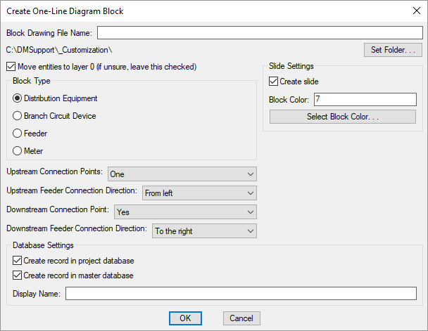
Create One-Line Diagram Block Dialog Box
-
Block Drawing File Name: The name of the drawing file for the block.
-
Folder: The folder where the block will be saved. The default location is your customization folder.
-
Press this button to change the folder where the block will be saved.
-
☐ Move entities to layer 0 Whether the entities you select for the block are moved to layer 0 or left on the layer they are currently on. If you are not sure what this means, leave this box checked.
Visit the help for AutoCAD for more information about setting layers in blocks.
-
🔘 Block Type The type of device that the one-line diagram block is used to represent.
If Feeder or Meter is selected, the connection point settings below will be disabled.
-
Upstream Connection Points: ▾ Sets the number of upstream connection points for the block.
If None is selected and an upstream connection is required on the one-line diagram, the feeder will connect to the insertion point of the block.
If the block will be used to represent transfer switches or UPSs, select Two.
-
Upstream Feeder Connection Direction: ▾ The direction from which the upstream feeder will connect to the block.
-
Downstream Connection Point: ▾ Whether the block has a downstream connection point.
If No is selected and a downstream connection is required on the one-line diagram, the feeder will connect to the insertion point of the block.
-
Downstream Feeder Connection Direction: ▾ The direction from which the downstream feeder will connect to the block.
Slide Settings
-
☐ Create slide Whether a slide for the block will be created automatically. The slide is used in the light fixture dialog boxes to display the graphics.
If you do not create a slide for a block, a preview will not be shown in the dialog boxes. The block will still display properly on the drawing.
You can manually create the slide later using the Create Slide command.
-
Block Color: The color to use for the block in the slide.
-
Press this button to set Block Color using the AutoCAD Select Color dialog box.
Database Settings
-
☐ Create record in project database Whether the block is added to the project database.
-
☐ Create record in master database Whether the block is added to the master database.
-
Display Name: The name of the block on the drawing and in the selected databases.
Creating the Block
Enter the information needed to create the one-line diagram block and press the button.
If Upstream Connection Points ▾ is set to any other value than None, you will be prompted to specify the upstream connection point for the block.
Specify upstream connection point:
If you set Upstream Connection Points ▾ to Two, you will be prompted to specify a second upstream connection point.
If Downstream Connection Point ▾ is set to Yes, you will then be prompted to specify the downstream connection point for the block.
Specify downstream connection point:
If 🔘 Block Type is set to Feeder or Meter, you will then be prompted to specify the mirroring point. This point is displayed as a grip when the block is inserted and is used to mirror the block.
Specify mirroring point:
The block, slide, and database records will be created for you. The entities selected for the block will be removed from the drawing.
If a slide is created, the screen will flash during the creation process. When it is finished, you should return to your original view of the drawing.