Insert Distribution Equipment Schedule Attribute
The
To insert a distribution equipment schedule attribute, go to
Ribbon:
Pulldown Menu:
Panel Schedule Attributes Dialog Box
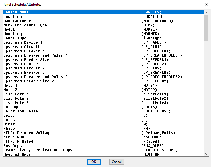
The dialog box is a list of attributes you can insert. Two values are listed in each row. The first value is a description of the attribute. The second value, in parenthesis, is the label of the attribute on the drawing. Use this value to compare what is already on your drawing with what is available to be inserted.
Select the attribute you want to insert and press the button. You will be prompted to specify the insertion point for the attribute.
The following fields are available to be inserted:
-
Device Name (PAN_KEY) Name of the distribution equipment. Specified in the distribution equipment definition. Visit the General Settings section for more information.
-
Location (LOCATION) Location of the distribution equipment. Specified in the distribution equipment definition. Visit the Notes Settings section for more information.
-
Manufacturer (MANUFACTURER) Manufacturer of the distribution equipment. Specified in the distribution equipment definition. Visit the Notes Settings section for more information.
-
NEMA Enclosure Type (NEMA) NEMA rating of the distribution equipment. Specified in the distribution equipment definition. Visit the Notes Settings section for more information.
-
Model (MODEL) Model of the distribution equipment. Specified in the distribution equipment definition. Visit the Notes Settings section for more information.
-
Mounting (MOUNTG) Mounting of the distribution equipment. Specified in the distribution equipment definition. Visit the General Settings section for more information.
-
Panel Type (iSubType) Lists the Main Disconnect Type ▾ for panels, switchboards, motor control centers, and meter centers. Lists the Type ▾ for enclosed breakers/disconnects and transfer switches. Specified in the distribution equipment definition. Visit the General Settings section for more information.
-
Upstream Device 1 (UP_PANEL1) Name of the distribution equipment connected to source 1. Set using the Connect Distribution Equipment in Database or Connect Distribution Equipment on One-Line Diagram command.
-
Upstream Circuit 1 (UP_CIR1) Circuit number connected to source 1. Set using the Connect Distribution Equipment in Database or Connect Distribution Equipment on One-Line Diagram command.
-
Upstream Breaker 1 (UP_BREAKER1) Size of the breaker connected to source 1. Specified in the distribution equipment definition. Visit the Feeder Specification Settings section for more information.
-
Upstream Breaker and Poles 1 (UP_BREAKERPOLES1) The breaker and numbers of poles connected to source 1. Specified in the distribution equipment definition. Visit the Feeder Specification Settings section for more information.
-
Upstream Feeder Size 1 (UP_FEEDER1) Feeder callout connected to source 1. Specified in the distribution equipment definition. Visit the Feeder Specification Settings section for more information.
-
Upstream Device 2 (UP_PANEL2) Name of the distribution equipment connected to source 2. Set using the Connect Distribution Equipment in Database or Connect Distribution Equipment on One-Line Diagram command. Source 2 is used for UPSs and transfer switches.
-
Upstream Circuit 2 (UP_CIR2) Circuit number connected to source 2. Set using the Connect Distribution Equipment in Database or Connect Distribution Equipment on One-Line Diagram command. Source 2 is used for UPS's and transfer switches.
-
Upstream Breaker 2 (UP_BREAKER2) Size of the breaker connected to source 2. Specified in the distribution equipment definition. Visit the Feeder Specification Settings section for more information. Source 2 is used for UPS's and transfer switches.
-
Upstream Breaker and Poles 2 (UP_BREAKERPOLES2) The breaker and numbers of poles connected to source 2. Specified in the distribution equipment definition. Visit the Feeder Specification Settings section for more information. Source 2 is used for UPS's and transfer switches.
-
Upstream Feeder Size 2 (UP_FEEDER2) Feeder callout connected to source 2. Specified in the distribution equipment definition. Visit the Feeder Specification Settings section for more information. Source 2 is used for UPS's and transfer switches.
-
Note 1 (NOTE1) Note 1 for the distribution equipment. Specified as the Header Note in the distribution equipment definition. Visit the Notes Settings section for more information.
-
Note 2 (NOTE2) Note 2 for the distribution equipment. Specified as the Footer Note in the distribution equipment definition. Visit the Notes Settings section for more information.
-
List Note 1 (sListNote1) List Note 1 for the distribution equipment. Specified in the distribution equipment definition. Visit the Notes Settings section for more information.
-
List Note 2 (sListNote2) List Note 2 for the distribution equipment. Specified in the distribution equipment definition. Visit the Notes Settings section for more information.
-
List Note 3 (sListNote3) List Note 3 for the distribution equipment. Specified in the distribution equipment definition. Visit the Notes Settings section for more information.
-
Voltage (VOLTS) The full voltage designation for the distribution equipment. It includes the voltage, the number of poles, and the number of wires. For example, 120V 1P 2W or 208V 3P 4W. Specified in the distribution equipment definition. Visit the General Settings section for more information.
-
Volts and Phase (VOLTS_PHASE) The voltage designation for the distribution equipment with the phase listed instead of the number of poles. For example, 120V 1-PH 2W or 208V 3-PH 4W. Specified in the distribution equipment definition. Visit the General Settings section for more information.
-
Volts (V) The voltage designation for the distribution equipment. Specified in the distribution equipment definition. Visit the General Settings section for more information.
-
Poles (P) The number of poles for the distribution equipment. Specified in the distribution equipment definition. Visit the General Settings section for more information.
-
Wires (W) The number of wires for the distribution equipment. Specified in the distribution equipment definition. Visit the General Settings section for more information.
-
Phase (PH) The number of phases for the distribution equipment. Specified in the distribution equipment definition. Visit the General Settings section for more information.
-
XFMR: Primary Voltage (sPrimaryVolts) Voltage of the transformer. Specified in the distribution equipment definition. Visit the General Settings section for more information. Only applies to transformers.
-
XFMR: kVA (dXFMRKva) kVA rating of the transformer. Specified in the distribution equipment definition. Visit the General Settings section for more information. Only applies to transformers.
-
XFMR: K-Rated (KRated) Whether the transformer is k-rated. Displays K-RATED if it is, nothing if it is not. Specified in the distribution equipment definition. Visit the General Settings section for more information. Only applies to transformers.
-
Bus Amps (BUS_AMPS) Bus amps of the distribution equipment. Specified in the distribution equipment definition. Visit the General Settings section for more information.
-
Frame Size / Vertical Bus Amps (OTHER_BUS_AMPS) Frame size or vertical bus amps of the distribution equipment. Frame size is used for enclosed breakers / disconnects. Vertical bus amps is used for motor control centers. This value is not used for other distribution equipment types. Specified in the distribution equipment definition. Visit the General Settings section for more information.
-
Neutral Amps (NEUT_AMP) Neutral amps of the distribution equipment. Specified in the distribution equipment definition. Visit the General Settings section for more information.
-
AIC Rating (AIC) AIC Rating of the distribution equipment. Specified in the distribution equipment definition. Visit the Fault Analysis Settings section for more information.
-
Total Fault (dFaultTotal) Total fault at the distribution equipment. Visit the Insert Fault Schedule section for information about how this is calculated.
-
Main Trip Amps (MAIN) Trip size of the main breaker. Displays MLO if the distribution equipment is main lugs only. Specified in the distribution equipment definition. Visit the General Settings section for more information.
-
Main Frame Amps (MAIN_FRAME) Frame size of the main breaker. Displays MLO if the distribution equipment is main lugs only. Specified in the distribution equipment definition. Visit the General Settings section for more information.
-
Lugs (LUGS) Lugs type of the distribution equipment. Specified in the distribution equipment definition. Visit the General Settings section for more information.
-
IG Bus (IG_BUS) Whether the distribution equipment has an IG bus. Displays ISO GND BUS if it does, nothing if it does not. Specified in the distribution equipment definition. Visit the General Settings section for more information.
-
UPS: Input kVA (INPUT_KVA) The kVA input of the distribution equipment. This value is only used for UPSs and phase inverters. Specified in the distribution equipment definition. Visit the General Settings section for more information.
-
UPS: Efficiency (EFFICIENCY) The efficiency of the distribution equipment. This value is only used for UPSs and phase inverters. Specified in the distribution equipment definition. Visit the General Settings section for more information.
-
UPS / Generator: kVA (KVA) The kVA output of the distribution equipment. This value is only used for UPSs, phase inverters, and generators. Specified in the distribution equipment definition. Visit the General Settings section for more information.
-
UPS / Generator: kW (KW) The kW output of the distribution equipment. This value is only used for UPSs, phase inverters, and generators. Specified in the distribution equipment definition. Visit the General Settings section for more information.
-
UPS / Generator: Power Factor (POWER_FACTOR) The power factor of the distribution equipment. This value is only used for UPSs, phase inverters, and generators. Specified in the distribution equipment definition. Visit the General Settings section for more information.
-
Circuit: Breaker Size / Poles (B1/B2) Breaker size and number of poles of the circuit.
-
Circuit: Breaker Size (BREAKERAMPS1/BREAKERAMPS2) Breaker size of the circuit.
-
Circuit: Poles (POLES1/POLES2) Number of poles of the circuit.
-
Circuit: Description (D1/D2) Circuit description of the circuit.
-
Circuit: Description End (DEND) The location where the circuit description wraps to a new line. The circuit description width is calculated based upon the distance between the D1/D2 and the DEND attributes.
-
Circuit: Total Load (L1/L2) The total load of the circuit, in kVA. It will include the load of all phases if it is a two- or three-phase load.
-
Circuit: Total Load (Amps) (L-AMPS1/L-AMPS2) The total load of the circuit, in amps. It will include the load of all phases if it is a two- or three-phase load.
-
Circuit: Phase Load (PL1/PL2) The phase load of the circuit in kVA.
-
Circuit: Phase Load (Amps) (PL-AMPS1/PL-AMPS2) The phase load of the circuit in amps.
-
Circuit: Feeder Size (F1/F2) The wire callout of the specific circuit. This value includes the size of the conduit and all of the wires.
-
Circuit: Wire Size (WIRE1/WIRE2) The phase wire size of the circuit.
-
Circuit: Receptacle Count (REC_COUNT1/REC_COUNT2) The number of receptacles connected to the circuit.
-
Circuit: Light Fixture Count (LTG_COUNT1/LTG_COUNT2) The number of light fixtures connected to the circuit.
-
Circuit: Equipment Connection Count (EQU_COUNT1/EQU_COUNT2) The number of equipment connections on the circuit.
-
Circuit: Underground (UNDERGROUND1/UNDERGROUND2) Whether the circuit is underground.
-
Circuit: Conduit (CONDUIT1/CONDUIT2) The conduit wire size of the circuit.
-
Circuit: Ground (GROUND1/GROUND2) The ground wire size of the circuit.
-
Total Lug Load (LUG_LOAD) The total lug load connected to the distribution equipment in kVA.
-
Lug Load, Phase A (LUG_PHA) The lug load on phase A in kVA.
-
Lug Load, Phase B (LUG_PHB) The lug load on phase B in kVA.
-
Lug Load, Phase C (LUG_PHC) The lug load on phase C in kVA.
-
Phase A KVA (PHA_KVA) The connected load on phase A in kVA.
-
Phase B KVA (PHB_KVA) The connected load on phase B in kVA.
-
Phase C KVA (PHC_KVA) The connected load on phase C in kVA.
-
Phase A Amps (100%) (PHA_AMP) The connected load on phase A in amps.
-
Phase B Amps (100%) (PHB_AMP) The connected load on phase B in amps.
-
Phase C Amps (100%) (PHC_AMP) The connected load on phase C in amps.
-
Phase A Amp Percentage (PHA_AMPPERCENTAGE) The percentage load of phase A compared to the average load on all phases.
-
Phase B Amp Percentage (PHB_AMPERCENTAGE) The percentage load of phase B compared to the average load on all phases.
-
Phase C Amp Percentage (PHC_AMPERCENTAGE) The percentage load of phase C compared to the average load on all phases.
Deprecated Attributes
Dynamic load calculation footers were added to distribution equipment schedules in Design Master Electrical 8.5. Prior to that release, the attributes described below were used to display load calculations in static footers. Visit the Design Master Electrical 8.5 Release Notes for more information about dynamic footers.
Using static footers is not recommended. Your load calculations are more likely to display incorrect values if you use static footers. If you choose to create and use your own static footers, the load type attributes described below are available for that purpose.
View Deprecated Attributes
- Connected General Lighting Load, Total (GEN_CON) The total connected general lighting load in kVA.
- Calculated General Lighting Load, Total (GEN_CAL) The total calculated general lighting load in kVA.
- Connected General Lighting Load, Table 120.45 Demand (GEN_TABLE_CON) The connected general lighting load in kVA for NEC Table 120.45 demand.
- Calculated General Lighting Load, Table 120.45 Demand (GEN_TABLE_CAL) The calculated general lighting load in kVA for NEC Table 120.45 demand.
- Connected General Lighting Load, Table 100% Demand (GEN_100_CON) The connected general lighting load in kVA for 100% demand.
- Calculated General Lighting Load, Table 100% Demand (GEN_100_CAL) The calculated general lighting load in kVA for 100% demand.
- Connected Lighting Load (LTG_CON) The connected lighting load in kVA.
- Calculated Lighting Load (LTG_CAL) The calculated lighting load in kVA. This value is 125% of the connected lighting load.
- Connected Largest Motor Load (LAR_CON) The connected largest motor load in kVA.
- Calculated Largest Motor Load (LAR_CAL) The calculated largest motor load in kVA. This value is 125% of the connected largest motor load.
- Largest Motor Load Multiplier (LAR_DIV) The load multiplier for the largest motor load as a percentage. Equal to calculated largest motor load divided by connected largest motor load.
- Connected Other Motor Load (MTR_CON) The connected load of all of the other motors in kVA.
- Calculated Other Motor Load (MTR_CAL) The calculated load of all of the other motors in kVA. This value is 100% of the connected load of all of the other motors.
- Connected Receptacle Load (REC_CON) The connected receptacle load in kVA.
- Calculated Receptacle Load (REC_CAL) The calculated receptacle load in kVA. This value is 100% of the first 10 kVA of receptacle load and 50% of the rest of the receptacle load.
- Connected Continuous Load (CON_CON) The connected continuous load in kVA.
- Calculated Continuous Load (CON_CAL) The calculated continuous load in kVA. This value is 125% of the connected continuous load.
- Connected Heating Load (HTG_CON) The connected heating load in kVA.
- Calculated Heating Load (HTG_CAL) The calculated heating load in kVA. This value is 100% of the connected heating load.
- Heating Load Multiplier (HTG_DIV) The load multiplier for the heating load as a percentage. Equal to calculated heating load divided by connected heating load.
- Connected Cooling Load (COL_CON) The connected cooling load in kVA.
- Calculated Cooling Load (COL_CAL) The calculated cooling load in kVA. This value is 100% of the connected heating load.
- Cooling Load Multiplier (COL_DIV) The load multiplier for the cooling load as a percentage. Equal to calculated cooling load divided by connected heating load.
- Connected Noncontinuous Load (NON_CON) The connected noncontinuous load in kVA.
- Calculated Noncontinuous Load (NON_CAL) The calculated noncontinuous load in kVA. This value is 100% of the connected noncontinuous load.
- Connected Kitchen Load (KIT_CON) The connected kitchen load in kVA.
- Calculated Kitchen Load (KIT_CAL) The calculated kitchen load in kVA. The value is based upon NEC Table 120.56. The table determines the demand factor based upon the number of units of kitchen equipment.
- Kitchen Load Multiplier (KIT_DIV) The demand factor for the calculated kitchen load. The value is based upon NEC Table 120.56. The table determines the demand factor based upon the number of units of kitchen equipment.
- Connected Diverse Load (DIV_CON) The connected diverse load in kVA.
- Calculated Diverse Load (DIV_CAL) The calculated diverse load in kVA.
- Diverse Load Multiplier (DIV_DIV) The load multiplier for the diverse load as a percentage. Each diverse device has this value set individually. Equal to calculated diverse load divided by connected diverse load.
- Connected Metered Demand Load (MD_CON) The connected metered demand load in kVA.
- Calculated Metered Demand Load (MD_CAL) The calculated metered demand load in kVA.
- Connected Future Demand Load (FUTURE_CON) The connected future demand load in kVA.
- Calculated Future Demand Load (FUTURE_CAL) The calculated future demand load in kVA.
- Future Demand Load Multiplier (FUTURE_DIV) The load multiplier for the future demand load as a percentage. Equal to calculated future demand load divided by connected future demand load.
- Connected School Load (SCH_CON) The connected school load in kVA.
- Calculated SchoolLoad (SCH_CAL) The calculated school load in kVA.
- School Load Multiplier (SCH_DIV) The load multiplier for the school load as a percentage. Equal to calculated school load divided by connected school load.
- Connected Residential Load (DGN_CON) The connected residential load in kVA.
- Calculated Residential Load (DGN_CAL) The calculated residential load in kVA.
- Connected Dwelling Unit General Load (DGT_CON) The connected general dwelling unit load in kVA.
- Calculated Dwelling Unit General Load (DGT_CAL) The calculated general dwelling unit load in kVA.
- Connected Multifamily Dwelling Unit General Lighting Load (DGL_CON) The connected general lighting load in kVA for a general multifamily dwelling unit.
- Connected Dwelling Unit Small Appliance Load (DSA_CON) The connected dwelling unit small appliance load in kVA.
- Calculated Dwelling Unit Small Appliance Load (DSA_CAL) The calculated dwelling unit small appliance load in kVA.
- Connected Dwelling Unit Laundry Load (DLA_CON) The connected dwelling unit laundry load in kVA.
- Calculated Dwelling Unit Laundry Load (DLA_CAL) The calculated dwelling unit laundry load in kVA.
- Connected Dwelling Unit Other Appliance Load (DOA_CON) The connected dwelling unit other appliance load in kVA.
- Connected Dwelling Unit Other Appliance Load, No Electric Co (DOA_NOKT_CON) The connected noncontinuous dwelling unit other appliance load in kVA.
- Connected Dwelling Unit Appliance Load (DAP_CON) The connected dwelling unit appliance load in kVA.
- Calculated Dwelling Unit Appliance Load (DAP_CAL) The calculated dwelling unit appliance load in kVA.
- Dwelling Unit Appliance Load Multiplier (DAP_DIV) The load multiplier for the dwelling unit appliance load as a percentage. Equal to calculated dwelling unit appliance load divided by connected dwelling unit appliance load.
- Connected Dwelling Unit Electric Dryer Load (DED_CON) The connected dwelling unit electric dryer load in kVA.
- Calculated Dwelling Unit Electric Dryer Load (DED_CAL) The calculated dwelling unit electric dryer load in kVA.
- Dwelling Unit Electric Dryer Load Multiplier (DED_DIV) The load multiplier for the dwelling unit electric dryer load as a percentage. Equal to calculated dwelling unit electric dryer load divided by connected dwelling unit electric dryer load.
- Connected Dwelling Unit Electric Cooking Load (DKT_CON) The connected dwelling unit electric cooking load in kVA.
- Calculated Dwelling Unit Electric Cooking Load (DKT_CAL) The calculated dwelling unit electric cooking load in kVA.
- Dwelling Unit Electric Cooking Load Multiplier (DAP_DIV) The load multiplier for the dwelling unit electric cooking load as a percentage. Equal to calculated dwelling unit electric cooking load divided by connected dwelling unit electric cooking load.
- Connected Dwelling Unit Heating Load (DEH_CON) The connected dwelling unit heating load in kVA.
- Calculated Dwelling Unit Heating Load (DEH_CAL) The calculated dwelling unit heating load in kVA.
- Dwelling Unit Heating Load Multiplier (DEH_DIV) The load multiplier for the dwelling unit heating load as a percentage. Equal to calculated dwelling unit heating load divided by connected dwelling unit heating load.
- Connected Dwelling Unit Heat Pump Load (DHP_CON) The connected dwelling unit heat pump load in kVA.
- Calculated Dwelling Unit Heat Pump Load (DHP_CAL) The calculated dwelling unit heat pump load in kVA.
- Dwelling Unit Heat Pump Load Multiplier (DHP_DIV) The load multiplier for the dwelling unit heat pump load as a percentage. Equal to calculated dwelling unit heat pump load divided by connected dwelling unit heat pump load.
- Connected Dwelling Unit Cooling Load (DCL_CON) The connected dwelling unit cooling load in kVA.
- Calculated Dwelling Unit Cooling Load (DCL_CAL) The calculated dwelling unit cooling load in kVA.
- Dwelling Unit Cooling Load Multiplier (DCL_DIV) The load multiplier for the dwelling unit cooling load as a percentage. Equal to calculated dwelling unit cooling load divided by connected dwelling unit cooling load.
- Dwelling Unit Heating and AC Load Maximum--NEC 120.82 (C) (DHM_CON) The dwelling unit heating and AC load maximum, per NEC 120.82 (C).
- Dwelling Unit Heating and AC Load Maximum Basis (DHM_BASIS) The dwelling unit heating and AC load maximum basis.
- Connected Multifamily Dwelling Unit Load (DWL_CON) The connected multifamily dwelling unit load in kVA.
- Calculated Multifamily Dwelling Unit Load (DWL_CAL) The calculated multifamily dwelling unit load in kVA.
- Multifamily Dwelling Unit Load Multiplier (DWL_DIV) The load multiplier for the multifamily dwelling unit load as a percentage. Equal to calculated multifamily dwelling unit load divided by connected multifamily dwelling unit load.
- Connected Multifamily Dwelling House Load (DHS_CON) The connected multifamily dwelling house load in kVA.
- Calculated Multifamily Dwelling House Load (DHS_CAL) The calculated multifamily dwelling house load in kVA.
- Dwelling Units (DWELLING_UNITS) The number of dwelling units.
- Total Area (TOTAL_AREA) The total area in square feet.
- Total 120.45 Demand Area (TABLE_AREA) The total area for NEC Table 120.45 demand in square feet.
- Total 100% Demand Area (100_AREA) The total area for 100% demand in square feet.
- 0.25 VA / sf Area, 120.45 Demand (AREA_025) The 0.25 VA/sf area for NEC Table 120.45 demand.
- 0.25 VA / sf Area, 100% Demand (AREA_025_100) The 0.25 VA/sf area for 100% demand.
- 0.5 VA / sf Area, 120.45 Demand (AREA_05) The 0.5 VA/sf area for NEC Table 120.45 demand.
- 0.5 VA / sf Area, 100% Demand (AREA_5_100) The 0.5 VA/sf area for 100% demand.
- 1 VA / sf Area, 120.45 Demand (AREA_1) The 1 VA/sf area for NEC Table 120.45 demand.
- 1VA / sf Area, 100% Demand (AREA_1_100) The 1 VA/sf area for 100% demand.
- 2 VA / sf Area, 120.45 Demand (AREA_2) The 2 VA/sf area for NEC Table 120.45 demand.
- 2 VA / sf Area, 100% Demand (AREA_2_100) The 2 VA/sf area for 100% demand.
- 3 VA / sf Area, 120.45 Demand (AREA_3) The 3 VA/sf area for NEC Table 120.45 demand.
- 3 VA / sf Area, 100% Demand (AREA_3_100) The 3 VA/sf area for 100% demand.
- 3.5 VA / sf Area, 120.45 Demand (AREA_35) The 3.5 VA/sf area for NEC Table 120.45 demand.
- 3.5 VA / sf Area, 100% Demand (AREA_35_100) The 3.5 VA/sf area for 100% demand.
- Custom Load 1: Name (LT1_DESC) The name of custom load 1.
- Custom Load 1: Connected Load (LT1_CON) The connected custom load 1 in kVA.
- Custom Load 1: Calculated (LT1_CAL) The calculated custom load 1 in kVA.
- Custom Load 1: Demand Factor (LT1_DIV) The demand factor of custom load 1. Equal to calculated custom load 1 divided by connected custom load 1.
- Custom Load 2: Name (LT2_DESC) The name of custom load 2.
- Custom Load 2: Connected Load (LT2_CON) The connected custom load 2 in kVA.
- Custom Load 2: Calculated (LT2_CAL) The calculated custom load 2 in kVA.
- Custom Load 2: Demand Factor (LT2_DIV) The demand factor of custom load 2. Equal to calculated custom load 2 divided by connected custom load 2.
- Connected KVA (KVA_CON) The total connected load in kVA.
- Calculated KVA (KVA_CAL) The total calculated load in kVA.
- Connected Amps (CON_AMPS) The total connected load in amps. Calculated using the total connected load in kVA and assuming a balanced load. Does not take into account any phase imbalance.
- Calculated Amps (TOTAL_AMPS) The total calculated load in amps. Calculated using the total calculated load in kVA and assuming a balanced load. Does not take into account any phase imbalance.