Edit Fault Schedule List
To edit fault schedule project settings, go to
Ribbon: ![]() Fault Schedule Label Group
Fault Schedule Label Group
Pulldown Menu:
To edit fault schedule standards settings, go to
Ribbon: ![]() Fault Schedule Label Group
Fault Schedule Label Group
Pulldown Menu:
Fault Current Schedule Label Display and Order Dialog Box
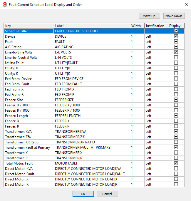
Visit the Common Label and Schedule Information section for more information about using the and buttons and the Key ☰, Label, Width, Justification ▾, and ☐ Display fields.
Values in the Key ☰ column are listed alphabetically below.
-
AIC Rating The AIC rating for the device. This value is set in the device definition.
-
Device The distribution equipment to which the row of fault information corresponds. Devices are listed in the order they are connected, starting at the utility. Devices that are connected to other devices are indented to indicate their relationship.
tipIf the names of the devices extend beyond the edge of the column because of the indentation, increase the width of the column.
-
Direct Motor: Fault The fault in amps at the device for all of the motors directly connected to the device.
The fault is 4 times the load of the motors. The XR ratio for motors is assumed to be 4. The motor is assumed to be directly connected to the device. There is no reduction in the motor fault for the branch circuit length.
-
Direct Motor: KVA The total load in kVA of all of the motors directly connected to the device. The fault from motors connected to other devices is reduced based upon the feeders connecting the devices.
-
Direct Motor: R The resistance of all of the motors directly connected to the device.
-
Direct Motor: X The reactance of all of the motors directly connected to the device.
-
Fault The total fault in amps at the device, including the fault from the utility and the fault from any motors in the system.
-
Fed From: Device The upstream device to which the device is connected.
-
Fed From: Fault The fault in amps at the upstream device to which the device is connected.
-
Fed From: R The resistance at the upstream device to which the device is connected.
-
Fed From: X The reactance at the upstream device to which the device is connected.
-
Feeder: Length The length of the feeder to the device.
-
Feeder: R The resistance of the feeder to the device, based upon the resistance per 1,000 feet of the feeder and the actual length of the feeder.
-
Feeder: R / 1000' The resistance of the feeder to the device per 1,000 feet.
-
Feeder: Size The wire size of the feeder connected to the device. This column lists the wire size of the phase conductors only.
-
Feeder: X The reactance of the feeder to the device based upon the reactance per 1,000 feet of the feeder and the actual length of the feeder.
-
Feeder: X / 1000' The reactance of the feeder to the device per 1,000 feet.
-
Line-to-Line Volts The line-to-line voltage for the device.
-
Line-to-Neutral Volts The line-to-neutral voltage for the device.
-
Total Motor: Fault The fault in amps at the device for all of the motors in the system.
-
Transformer: Fault at Primary The fault in amps at the primary of the transformer. This fault is based upon the primary voltage.
-
Transformer: KVA The size of the transformer in kVA. If the device is not a transformer, this field is left blank.
-
Transformer: R The resistance at the primary of the transformer.
-
Transformer: X The reactance at the primary of the transformer.
-
Transformer: XR Ratio The transformer XR ratio. If the device is not a transformer, this field is left blank.
-
Transformer: Z% The transformer impedance percentage. If the device is not a transformer, this field is left blank.
-
Utility: Fault The utility fault in amps at the device.
tipUse this column instead of the Fault column if you do not want to include motor contributions in your fault calculations.
-
Utility: X The reactance at the device from the utility current.
-
Utility: R The resistance at the device from the utility current.