Edit Panel List
To edit panel list project settings, go to
Ribbon:  Panel List Label Group
Pulldown Menu:
To edit panel list master settings, go to
Ribbon:
Pulldown Menu:
Panel List Label Display and Order Dialog Box
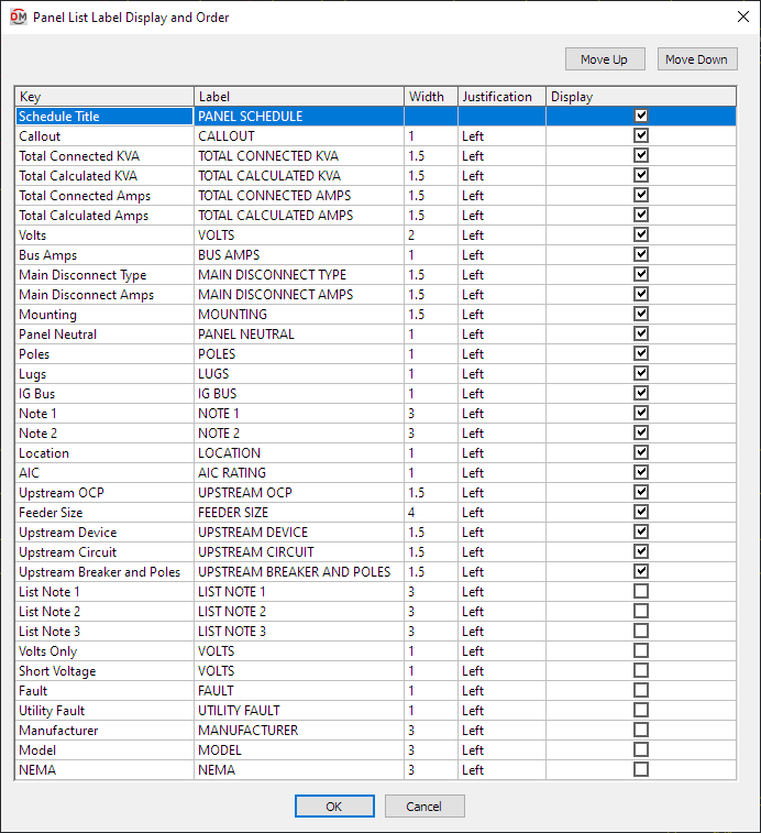
Visit the Common Label and Schedule Information section for more information about using the and buttons and the Key ☰, Label, Width, Justification ▾, and ☐ Display fields.
Values in the Key ☰ column are listed alphabetically below.
-
AIC This value is taken from the panel definition.
-
Bus Amps This value is taken from the panel definition.
-
Callout The name of the panel.
-
Fault The total fault in amps at the panel, including the fault from the utility and the fault from any motors in the system.
-
Feeder Size This value is taken from the panel definition.
-
IG Bus This value is taken from the panel definition.
-
List Note 1 This value is taken from the panel definition.
-
List Note 2 This value is taken from the panel definition.
-
List Note 3 This value is taken from the panel definition.
-
Location This value is taken from the panel definition.
-
Lugs This value is taken from the panel definition.
-
Main Disconnect Amps This value is taken from the panel definition.
-
Main Disconnect Type This value is taken from the panel definition.
-
Manufacturer This value is taken from the panel definition.
-
Model This value is taken from the panel definition.
-
Mounting This value is taken from the panel definition.
-
NEMA This value is taken from the panel definition.
-
Note 1 This value is taken from the panel definition.
-
Note 2 This value is taken from the panel definition.
-
Panel Neutral This value is taken from the panel definition.
-
Poles This value is taken from the panel definition.
-
Short Voltage The voltage value and poles of the panel.
Examples: 120V 1P, 208V 2P
-
Total Calculated Amps The total calculated load in amps of the panel.
-
Total Calculated KVA The total calculated load in kVA of the panel.
-
Total Connected Amps The total calculated load in amps of the panel.
-
Total Connected KVA The total calculated load in kVA of the panel.
-
Upstream Breaker and Poles The size of the breaker and number of poles for the panel feeder.
Examples: 20/1, 30/3
-
Upstream Circuit The circuit to which the panel is connected on the upstream device.
-
Upstream Device The upstream device to which the panel is connected.
-
Upstream OCP This value is taken from the panel definition.
-
Utility Fault The utility fault in amps at the panel.
tipUse this column instead of the Fault column if you do not want to include motor contributions.
-
Volts The full voltage value of the panel. The volts, poles, and wires will be displayed.
Examples: 120V 1P 2W, 208V 2P 2W
-
Volts Only The voltage value of the panel. Only the volts will be displayed. The poles and wires will not be displayed.
Examples: 120V, 208V