Options
The
Visit the General Customization Commands section for more information about how the
To edit the options project list, go to
Ribbon: ![]() Options
Options
Pulldown Menu:
To edit the options standards list, go to
Ribbon: ![]() Options
Options
Pulldown Menu:
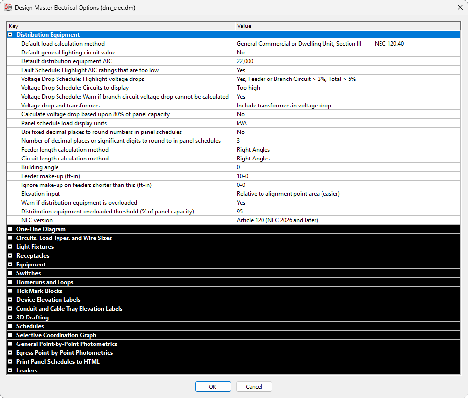
Design Master Electrical Options Dialog Box
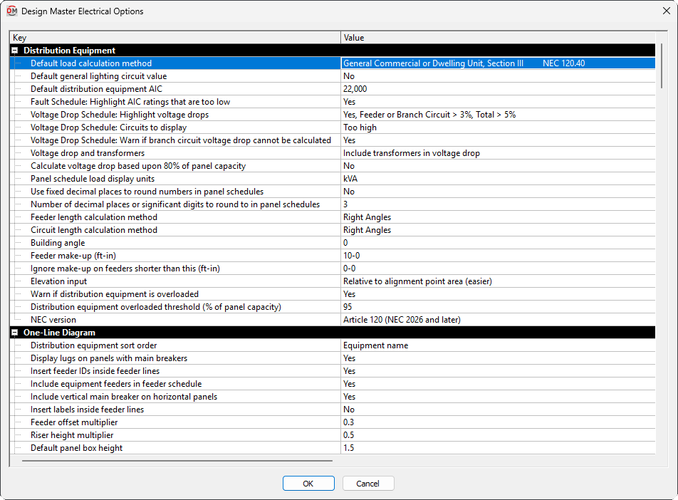
The Design Master Electrical Options dialog box contains a list of all of the options and their current settings. The options are arranged in groups in the list.
Editing a Setting
To edit an option setting, select the Value ☰ in the list and enter a new value.
Press the button to save your changes.
If the change you made to the options does not immediately appear on the drawing, run the Coordinate Drawings and Database command. This command will update the drawing to use the new settings you have specified.
Distribution Equipment
-
Default load calculation method ▾ When a new distribution equipment is created, the calculation method for load types is set to this value. Visit the Feeder and Service Calculation Settings section for more information.
-
Default general lighting circuit value ▾ When a new distribution equipment is created, the default general lighting setting for circuits on the equipment is set to this value. Visit the Feeder and Service Calculation Settings section for more information.
-
Default distribution equipment AIC When a new distribution equipment is created, the AIC rating is set to this value. The value for each panel can be changed once it is created.
-
Fault Schedule: Highlight AIC ratings that are too low ▾ Whether AIC ratings that are too low are highlighted in the fault schedule. Visit the Insert Fault Schedule section for more information.
-
Voltage Drop Schedule: Highlight voltage drops ▾ Whether voltage drops that are too high are highlighted in the voltage drop schedule. Visit the Insert Voltage Drop Schedule section for more information.
-
Voltage Drop Schedule: Circuits to display ▾ Which circuits are displayed in the voltage drop schedule. Visit the Insert Voltage Drop Schedule section for more information.
-
Voltage Drop Schedule: Warn if branch circuit voltage drop cannot be calculated ▾ Whether a warning is displayed if the branch circuit voltage drop cannot be calculated correctly due to circuiting errors. Visit the Insert Voltage Drop Schedule section for more information.
-
Voltage drop and transformers ▾ How voltage drop is calculated through transformers. Visit the Voltage Drop and Transformers Options article in the knowledge base for more information.
- Ignore transformers The voltage drop through the transformer is ignored when the voltage drop for the system is calculated. The voltage drop through the upstream feeders is carried through the transformer.
- Reset voltage drop at transformers The voltage drop is reset to 0% at each transformer. The voltage drop through the transformer is ignored. The voltage drop through the upstream feeders is ignored.
- Include transformers in voltage drop The voltage drop through the transformer is calculated and added to the voltage drop on the feeder. The voltage drop through the upstream feeders is carried through the transformer.
After changing the Voltage drop and transformers ▾ option, reinsert the voltage drop schedule on the drawing to display voltage drop numbers based upon the new setting. Visit the Insert Voltage Drop Schedule section for more information about inserting the schedule.
-
Calculate voltage drop based upon 80% of panel capacity ▾ Whether calculations for the voltage drop schedule are based upon 80% of panel capacity or actual panel loads. Visit the Insert Voltage Drop Schedule section for more information.
-
Panel schedule load display units ▾ The units used for displaying loads on panel schedules.
- kVA The loads are displayed in kVA.
- VA The loads are displayed in VA.
- Amps The loads are displayed in amps.
warningChanging this value will change the numbers, but it will not change the column labels and headers. You will need to manually customize the distribution equipment schedule blocks. Visit the Distribution Equipment Schedule Blocks section for more information.
-
Use fixed decimal places to round numbers in panel schedules ▾ How values are rounded when they are displayed on distribution equipment schedules.
The amount of rounding is based upon the Number of decimal places or significant digits to round to in panel schedules option.- Yes Numbers in distribution equipment schedules will include a fixed number of digits after the decimal, rounding when needed.
- No Numbers in distribution equipment schedules will be rounded to a fixed number of significant figures.
-
Number of decimal places or significant digits to round to in panel schedules The number of fixed decimal places to display for values in distribution equipment schedules, or the number of significant digits to which numbers will be rounded, depending upon the setting in the Use fixed decimal places to round numbers in panel schedules ▾ option.
-
Feeder length calculation method ▾ When a new distribution equipment is created, the calculation method for feeder length is set to this value. Visit the Feeder Length Settings section for more information.
-
Circuit length calculation method ▾ When a new distribution equipment is created, the calculation method for circuit length is set to this value. Visit the Set Circuit Information section for more information.
-
Building angle When a new distribution equipment is created, the building angle used for feeder and circuit length calculations is set to this value. Visit the Feeder Length Settings section and the How Building Angle Affects Calculations article in the knowledge base for more information.
-
Feeder make-up The extra length of wire included in feeder lengths to account for the wire used for distribution equipment connections. It is used in the fault calculation, voltage drop calculation, and takeoffs. Visit the Distance Input Format section for more information about specifying this length.
-
Ignore make-up on feeders shorter than this If two pieces of distribution equipment are close to each other, additional feeder length is not needed to terminate the wires. If the distance between distribution equipment is shorter than the specified value, the value set for the Feeder make-up option is not added to the length of the feeder. Visit the Distance Input Format section for more information about specifying this length.
-
Elevation input ▾ When distribution equipment is inserted on the drawing, the elevation input method is set to this value. Visit the Elevation section for more information.
-
Warn if distribution equipment is overloaded ▾ Whether a warning is displayed if you have distribution equipment in the project that is overloaded. Visit the Overloaded Distribution Equipment section for more information.
This setting will affect the project for all users. To change this setting for a single user, visit the User Options section.
-
Distribution equipment overloaded threshold (% of panel capacity) When the load on a distribution equipment exceeds this value as a percentage of the load capacity, the distribution equipment will be considered overloaded.
-
NEC version ▾ Which NEC reference numbers are used in panel schedule footers for load calculations.
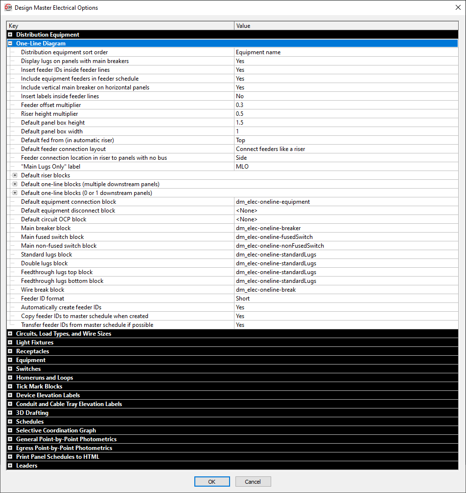
One-Line Diagram
-
Distribution equipment sort order ▾ The order in which downstream equipment connections are inserted when generating the one-line diagram.
- Breaker size Equipment will be inserted by breaker size from largest to smallest. Equipment with the same breaker size will be inserted in alphabetical order.
- Circuit number Equipment will be inserted by circuit number beginning with circuit 1. Equipment downstream from panels will be inserted beginning with odd circuits, then even circuits.
- Distance Equipment will be inserted based upon the distance between the upstream and downstream equipment from nearest to farthest.
- Equipment name Equipment will be inserted by name in alphabetical order.
-
Display lugs on panels with main breakers ▾ Whether lugs are displayed on panels with main breakers.
- Yes Lugs are displayed on all bus bars.
- No Lugs are not displayed on bus bars with main breakers.
This option does not change whether the lugs exist on the panel, only whether they are displayed.
-
Insert feeder IDs inside feeder lines ▾ Whether feeder IDs appear on the one-line diagram.
-
Include equipment feeders in feeder schedule ▾ Whether feeders to equipment connections are included on the feeder schedule.
If Insert feeder IDs inside feeder lines ▾ is set to Yes, this option will be set to Yes. If Insert feeder IDs inside feeder lines ▾ is set to No, equipment connection feeders will only appear on the feeder schedule if they are labeled manually.
-
Include vertical main breaker on horizontal panels ▾ Whether the main breaker on a horizontal custom panel block is inserted vertically.
- Yes The main breaker is inserted perpendicular to the horizontal panel bus.
- No The main breaker is inserted along the horizontal panel bus.
-
Insert labels inside feeder lines ▾ Whether feeder labels can snap to inside feeder lines when being inserted.
-
Feeder offset multiplier This value sets the default distance when offsetting feeders. This value is multiplied by DIMSCALE to determine the distance.
-
Riser height multiplier This value sets the default distance between elevations when generating a riser diagram.
-
Default panel box height When inserting a custom block on the diagram, the Specific Panel Box Size height is set to this value. Visit the Insert Distribution Equipment section for more information.
-
Default panel box width When inserting a custom block on the diagram, the Specific Panel Box Size width is set to this value. Visit the Insert Distribution Equipment section for more information.
-
Default fed from (in automatic riser) ▾ Whether distribution equipment blocks are fed from the top or the bottom when generating a riser diagram.
-
Default feeder connection layout ▾ Sets how feeders are drawn for distribution equipment inserted into the diagram using the Insert Distribution Equipment command. This option can also be set in the Insert Distribution Equipment dialog box.
-
Feeder connection location in riser to panels with no bus ▾ Sets how feeders are drawn for distribution equipment blocks with no bus when generating a riser diagram.
-
"Main Lugs Only" label Sets the text for the Main Trip Amps, Main Trip Amps (MLO), and Main Trip Amps and Poles labels when the Main Disconnect ▾ for the distribution equipment is set to Main Lugs Only.
-
Default riser blocks Sets the default blocks for each distribution equipment type when generating a riser diagram.
-
Default one-line blocks (multiple downstream panels) Sets the default blocks for each distribution equipment type that is connected to two or more downstream distribution equipment when generating a one-line diagram.
- <Same as Riser Block> Uses the same default block as the corresponding Default riser blocks option.
-
Default one-line blocks (0 or 1 downstream panels) Sets the default blocks for each distribution equipment type that is connected to one or fewer downstream distribution equipment when generating a one-line diagram.
- <Same as Riser Block> Uses the same default block as the corresponding Default riser blocks option.
-
Default equipment connection block Sets the default block for equipment connections on the one-line diagram.
-
Default equipment disconnect block Sets the default block for the equipment disconnect on the one-line diagram.
-
Default circuit OCP block Sets the default block for OCP on the one-line diagram.
-
Main breaker block Sets the default block for main breakers on the one-line diagram.
-
Main fused switch block Sets the default block for main fused switches on the one-line diagram.
-
Main non-fused switch block Sets the default block for main non-fused switches on the one-line diagram.
-
Standard lugs block Sets the default block for standard lugs on the one-line diagram.
-
Double lugs block Sets the default block for double lugs on the one-line diagram.
-
Feedthrough lugs top block Sets the default block for feedthrough lugs connected at the top on the one-line diagram.
-
Feedthrough lugs bottom block Sets the default block for feedthrough lugs connected at the bottom on the one-line diagram.
-
Wire break block Sets the default block for wire breaks on the one-line diagram.
-
Feeder ID format ▾ Sets how feeder IDs are generated. Visit the Feeder IDs article in the knowledge base for more information.
-
Automatically create feeder IDs ▾ Whether feeder IDs are automatically generated.
- Yes Feeder IDs are generated automatically based upon the Feeder ID format ▾.
- No When a feeder ID is generated, the New Feeder Callout ID dialog box will open. You can then set the feeder ID, feeder ID group, whether feeder IDs should be automatically generated in the future, and whether the feeder ID should be added to the master schedule.
-
Copy feeder IDs to master schedule when created ▾ Whether feeder IDs are copied to the master schedule when they are generated.
-
Transfer feeder IDs from master schedule if possible ▾ When a feeder ID is generated with the same specifications as an existing feeder ID in the master schedule, this option sets whether a new feeder ID is generated or the existing feeder ID is used.
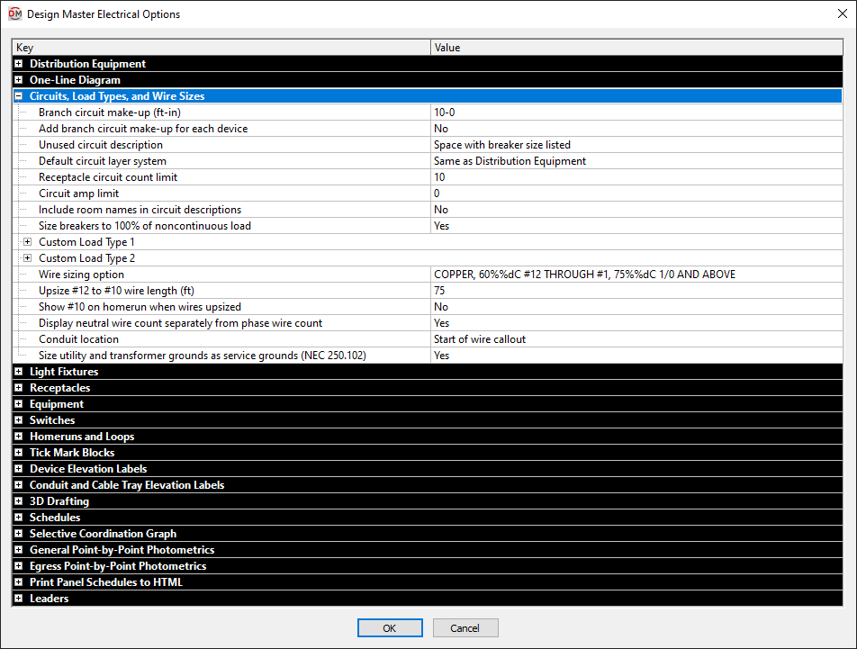
Circuits, Load Types, and Wire Sizes
-
Branch circuit make-up This value is the extra length of wire included in branch circuit lengths to account for branch circuit connections. It is used in the fault calculation, voltage drop calculation, and takeoffs. Visit the Distance Input Format section for more information about specifying this length.
-
Add branch circuit make-up for each device ▾ Whether the length specified in Branch circuit make-up is added for each device on the circuit.
- Yes The make-up added to the branch circuit length is multiplied for each device on the circuit.
- No The make-up is only added to the branch circuit length once, regardless of the number of devices on the circuit.
-
Unused circuit description ▾ Specifies how circuits that do not have any devices connected to them are labeled in the panel schedule.
- Space with breaker size listed The circuit description is set to SPACE. The breaker size is displayed as the smallest default breaker.
- Space with no breaker listed The circuit description is set to SPACE. The breaker size is displayed as a dash.
- Spare with breaker size listed The circuit description is set to SPARE. The breaker size is displayed as the smallest default breaker.
- Spare with no breaker listed The circuit description is set to SPARE. The breaker size is displayed as a dash.
- Dash with no breaker listed The circuit description is displayed as a dash. The breaker size is displayed as a dash.
After changing this option, use the Update Distribution Equipment Schedule command to update any panel schedules on the drawing.
-
Default circuit layer system ▾ The default layer system associated with circuits and taps on panels.
- Same as Distribution Equipment The circuits will use the same layer system as the distribution equipment with which they are associated.
- <Layer System> The circuits will use the specific layer system chosen.
This default setting can be overridden for specific circuits using the Circuiting dialog box. Visit the Circuiting section for more information about setting the layer system for circuits.
-
Receptacle circuit count limit While circuiting receptacles, you will be alerted when attempting to place receptacles on a single circuit above this value. Once the receptacles are circuited, the alert will not be shown.
The count is based upon total load, not the number of devices. Every 0.18 kVA of load is counted as a receptacle. This way, a quad receptacle with 0.36 kVA that is inserted as a single receptacle is counted as two receptacles and not one.
The warning does not prevent you from connecting more receptacles to the circuit than specified for situations where that is necessary.
-
Circuit amp limit While circuiting devices, you will be alerted when the load in amps on a single circuit reaches this value. Once the devices are circuited, the alert will not be shown.
The warning does not prevent you from connecting more devices to the circuit than specified for situations where that is necessary.
-
Include room names in circuit descriptions ▾ Whether room names are included in circuit descriptions on panel schedules. If one of the Yes options is selected, all of the rooms containing a device on the circuit are listed in the description. Rooms must be inserted using the Create Room command.
- Yes, include "Room" in description The rooms are listed in the circuit description. The word Room and the room name is included in the description.
- Yes, do not include "Room" in description The rooms are listed in the circuit description. Only the room name is included in the description.
- No The rooms are not listed in the circuit description.
-
Size breakers to 100% of noncontinuous load ▾ Whether branch circuits are sized to 100% of noncontinuous loads (per NEC 210.20(A)) or to 125% of noncontinuous loads.
- Yes Branch circuits are sized to 100% of noncontinuous loads and 125% of continuous loads. This setting will result in smaller breakers and wire sizes.
- No Branch circuits are sized to 125% of all loads. This setting will result in larger breakers and wire sizes.
The following load types are noncontinuous and will be affected by this option:
- Receptacles (NEC Handbook Exhibit 120.4)
- Noncontinuous
- Kitchen
- Diverse
- Small Appliance
- Laundry
- Appliance, Noncontinuous
- Electric Dryer
- Electric Cooking
- Marina / Mobile Home / RV
The following load types are continuous and will not be affected by this option (All motors are considered continuous at the branch circuit level):
- Lighting
- Largest Motor (NEC 430.24)
- Other Motors (NEC 430.24)
- Continuous
- Heating (NEC 424.5)
- Cooling, Largest Motor (NEC 430.24)
- Cooling, Other Motors (NEC 430.24)
- Heating and Cooling Motor (NEC 430.24)
- Appliance, Continuous
- Appliance Motor (NEC 430.24)
- Dwelling Unit Heating (NEC 424.5)
- Dwelling Unit Cooling, Largest Motor (NEC 430.24)
- Dwelling Unit Cooling, Other Motors (NEC 430.24)
- Dwelling Unit Heating and Cooling Motor (NEC 430.24)
-
Custom Load Type 1 / Custom Load Type 2 Two custom load types are provided to define load types that are not otherwise specified in the software. The settings for each custom load type are the same.
-
Name The name of the custom load type. It is displayed when selecting the load type for a device and it is printed on the distribution equipment schedule load summary.
-
Calculation method ▾ The method used for setting the demand factor for the load type.
- Fixed demand factor The demand factor for the load is constant and fixed. (Most of the default load types are fixed.)
- Variable demand factor The demand factor varies depending upon the load. (For example, kitchen and diverse load types.)
- Variable calculated load The demand factor varies, but the calculated load is input rather than the demand factor.
-
Demand factor The demand factor for the load type. Enabled if Calculation method ▾ is set to Fixed demand factor.
-
Load type ▾ Whether the load type should be treated as a nontinuous or noncontinuous load for branch circuit sizing.
-
-
Wire sizing option ▾ Which sizing option is selected in the Wire Sizing dialog box. Visit the Wire Sizing section for more information about creating and modifying wire sizing tables. This option is most useful in standards database to set the default sizing option for new projects.
-
Upsize #12 to #10 wire length Branch circuits that are sized to #12 and exceed this length are automatically upsized to #10 wire.
tipIf you have two otherwise identical circuits, and one has #12 wire while the other has #10 wire, this option is the most likely cause of the difference.
-
Show #10 on homerun when wires upsized ▾ If a branch circuit is upsized through the Upsize #12 to #10 wire length option, this option controls whether a #10 is displayed next to upsized homeruns on the drawing.
-
Display neutral wire count separately from phase wire count ▾ Whether the neutral wire and phase wires are counted separately on wire callouts when they are the same size.
-
Conduit location ▾ Whether the conduit is listed at the start or end of wire callouts.
-
Size utility and transformer grounds as service grounds ▾ Whether the ground for utilities and transformers is sized as a service ground or an equipment ground.
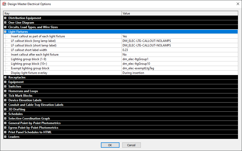
Light Fixtures
-
Insert callout as part of each light fixture ▾ Whether the light fixture callout is automatically inserted as part of each light fixture on the drawing.
-
LF callout block (long lamp label) The block used for the Insert Light Fixture Callout command when the lamp label is wider than the value specified in LF callout short label width.
-
LF callout block (short lamp label) The block used for the Insert Light Fixture Callout command when the lamp label is smaller than the value specified in LF callout short label width.
-
LF callout short label width This width is used to determine which LF callout block is inserted for a light fixture.
-
Insert callout after each light fixture ▾ Whether you will be prompted to insert a light fixture callout after each light fixture on the drawing. The light fixture callout that is inserted is the same as what is inserted using the Insert Light Fixture Callout command.
-
Lighting group block (1-9) The callout block used when you associate a light fixture with a lighting group and the group number is less than 10.
-
Lighting group block (10+) The callout block used when you associate a light fixture with a lighting group and the group number is 10 or more.
-
Exempt lighting group block The block used when a light fixture is marked as exempt.
tipTo not insert a block with light fixtures that are exempt, leave this value blank.
-
Display light fixture overlay ▾ When a light fixture overlay will be displayed on non-plotting layers.
- Never Light fixture overlays will never be inserted.
- During insertion The overlay will be displayed only while the light fixture is being inserted. Once the light fixture is inserted, the overlay will not be displayed. To view the overlay again, you must insert a new fixture.
- Always The light fixture overlay will be displayed during insertion and will be inserted with the light fixture.
The light fixture overlay is only generated for fixtures that meet the following criteria:
- The ☐ General Light checkbox or ☐ Egress Light checkbox must be checked.
- The Elevation must be higher than 0.
- An IES file must be associated with the fixture.
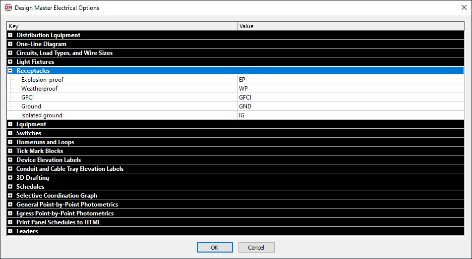
Receptacles
-
Explosion-proof This label is inserted with receptacles that have the ☐ Explosion-proof box checked in the receptacle schedule.
-
Weatherproof This label is inserted with receptacles that have the ☐ Weatherproof box checked in the receptacle schedule.
-
GFCI This label is inserted with receptacles that have the ☐ GFCI box checked in the receptacle schedule.
-
Ground This label is inserted with receptacles that have the ☐ Ground box checked in the receptacle schedule.
-
Isolated ground This label is inserted with receptacles that have the ☐ Isolated Ground box checked in the receptacle schedule.
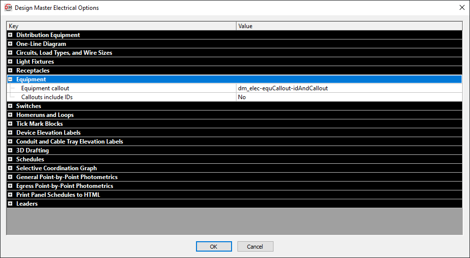
Equipment
-
Equipment callout ▾ The information that is displayed on the callout for each piece of equipment. Visit the How to Use or Create a Custom Equipment Callout article in the knowledge base for more information.
- Display callout, kVA and HP The equipment callout contains two lines. The top line displays the callout. The bottom line displays the loads on the equipment and the voltage. Motor loads with a horsepower value set are displayed in horsepower. All other loads are displayed in kVA.
- Display callout, amps, and HP The equipment callout contains two lines. The top line displays the callout. The bottom line displays the loads on the equipment and the voltage. Motor loads with a horsepower value set are displayed in horsepower. All other loads are displayed in amps.
- Display callout and amps only The equipment callout contains two lines. The top line displays the callout. The bottom line displays the loads on the equipment and the voltage. All loads are displayed in amps.
- Display callout only The equipment callout contains a single line that displays the callout.
- No callout No equipment callout is inserted on the drawing.
- Select custom block Select this option to choose a custom block for your equipment callout. Once a block is selected, the block name will be displayed.
-
Callouts include IDs ▾ Whether the equipment ID is displayed when using a custom equipment callout block that includes the ID attribute.
- Yes The ID attribute in the callout will display the equipment ID.
- No The ID attribute in the callout will display 0.
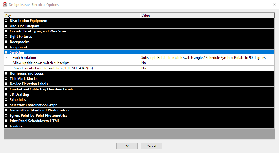
Switches
-
Switch rotation ▾ This option controls how switches and switch subscripts are rotated. Switch subscripts should be rotated to match the angle of the switch. Switches in the schedule should be rotated so that the $ is drawn vertical. The correct option to make this happen depends upon how you have your switch blocks defined.
If you are not sure which option to choose, choose an option and insert a switch schedule on the drawing to see how it looks. Try each option until you find one that looks correct.
- Subscript: Rotate to match switch angle /
Schedule Symbol: Rotate to 90 degrees The switch subscript is inserted at the same rotation angle as the switch. The switch in the schedule is rotated 90 degrees. Choose this option if your switch rotation is set perpendicular to the wall. - Subscript: Rotate to match switch angle + 90 degrees /
Schedule Symbol: Rotate to 0 degrees The switch subscript is rotated 90 degrees relative to the switch. The switch in the schedule is not rotated. Choose this option if your switch rotation is set parallel to the wall. - Subscript: Rotate to match switch angle - 90 degrees /
Schedule Symbol: Rotate to 180 degrees The switch subscript is rotated -90 degrees relative to the switch. The switch in the schedule is rotated -90 degrees. Choose this option if your switch rotation is set parallel to the wall. - Subscript: Rotate to 0 /
Schedule Symbol: Rotate to 0 degrees The switch subscript is not rotated. The switch in the schedule is not rotated. Choose this option if your switch rotation is set parallel to the wall and you do not want the switch subscript rotated automatically. - Subscript: Rotate to 0 /
Schedule Symbol: Rotate to 90 degrees The switch subscript is not rotated. The switch in the schedule is rotated 90 degrees. Choose this option if your switch rotation is set perpendicular to the wall and you do not want the switch subscript rotated automatically.
- Subscript: Rotate to match switch angle /
-
Allow upside down switch subscripts ▾ Whether switch subscripts can be displayed upside down.
- Yes The switch subscript will be rotated the same way as the switch. If the switch is upside down, the subscript will be upside down.
- No The switch subscript will first be rotated in the same way as the switch. If the text is upside down, it will then be rotated an additional 180 degrees so that it is readable.
-
Provide neutral wire to switches ▾ Whether a neutral wire is provided to switches.
warningFor projects to comply with 2011 NEC 404.2(C), this option must be set to Yes.
Homeruns and Loops

-
Hot or neutral first ▾ Whether the hot or neutral ticks marks are displayed closer to the homerun arrowhead in groups of tick marks.
-
Ground location ▾ Sets whether the ground wire tick mark is displayed closest to or farthest from the homerun arrowhead in groups of tick marks.
-
Draw loops ▾ How loops are drawn between devices. Visit the Set Looping Options section for more information about the available options.
-
Loop to same circuit first on combined homeruns (light fixtures) ▾ How loops are drawn on combined homeruns containing light fixtures. Visit the Set Looping Options section for more information.
-
Loop to same circuit first on combined homeruns (other devices) ▾ How loops are drawn on combined homeruns containing devices other than light fixtures. Visit the Set Looping Options section for more information.
-
Homerun wire callouts and tick marks ▾ Sets when wire callouts and/or tick marks are displayed on homeruns.
- Tick marks for all homeruns Tick marks are displayed on all homeruns. Wire callouts are not displayed on homeruns.
- Tick marks for #12, wire callouts if > #12 Tick marks are displayed if the wires are #12. Wire callouts are displayed if the wires are #10 or larger.
- Tick marks for #12, tick marks and wire callouts if > #12 Tick marks are displayed if the wires are #12. Wire callouts and tick marks are displayed if the wires are #10 or larger.
- Tick marks for #12 1-pole, wire callouts for all others Tick marks are displayed if the wires are #12 and the distribution equipment has one pole. Wire callouts are displayed if the wires are #10 or larger, or if the wires are #12 and the distribution equipment has two or three poles.
- Wire callouts for all homeruns Wire callouts are displayed on all homeruns. Tick marks are not displayed on homeruns.
- No wire callouts or tick marks Wire callouts and tick marks are not displayed on homeruns.
- Nothing for #12, wire callouts if > #12 Wire callouts and tick marks are not displayed if the wires are #12. Wire callouts are displayed if the wires are #10 or larger.
-
Display tick marks on loops ▾ Whether tick marks are displayed on loops between devices.
-
Multiple arrowheads on combined homeruns ▾ Whether combined homeruns display a single arrowhead or one arrowhead for each circuit on the homerun.
-
Share neutrals on combined homeruns ▾ Whether neutrals on combined homeruns are shared.
warningFor projects to comply with the 2008 NEC, this option must be set to No. To share neutrals in accordance with the 2008 NEC, create a multiple-pole breaker and use the button in the Circuiting command.
-
Circuit break block The block that is used when circuits are broken. Use the None setting if you do not want a block displayed on broken circuits.
-
Homerun arrow block The block used for homerun arrowheads.
-
Homerun arrow length The length of the homerun arrowhead.
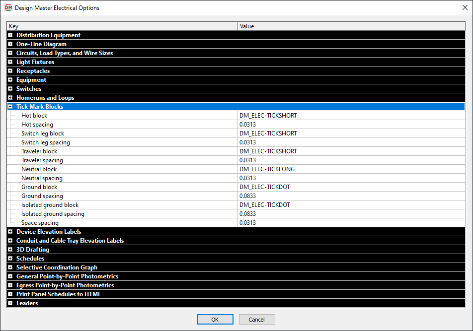
Tick Mark Blocks
-
Hot block The block used for tick marks representing the hot wires.
-
Hot spacing The distance between hot tick marks and other tick marks. This value is multiplied by DIMSCALE to get the final tick mark spacing distance.
-
Switch leg block The block used for tick marks representing the switch leg wires.
-
Switch leg spacing The distance between switch leg tick marks and other tick marks. This value is multiplied by DIMSCALE to get the final tick mark spacing distance.
-
Traveler block The block used for tick marks representing the traveler wires.
-
Traveler spacing The distance between traveler tick marks and other tick marks. This value is multiplied by DIMSCALE to get the final tick mark spacing distance.
-
Neutral block The block used for tick marks representing the neutral wires.
-
Neutral spacing The distance between neutral tick marks and other tick marks. This value is multiplied by DIMSCALE to get the final tick mark spacing distance.
-
Ground block The block used for tick marks representing the ground wires.
-
Ground spacing The distance between ground tick marks and other tick marks. This value is multiplied by DIMSCALE to get the final tick mark spacing distance.
-
Isolated ground block The block used for tick marks representing the isolated ground wires.
-
Isolated ground spacing The distance between isolated ground tick marks and other tick marks. This value is multiplied by DIMSCALE to get the final tick mark spacing distance.
-
Space spacing The extra space inserted between tick marks when a space is included. This value is multiplied by DIMSCALE to get the final tick mark spacing distance.
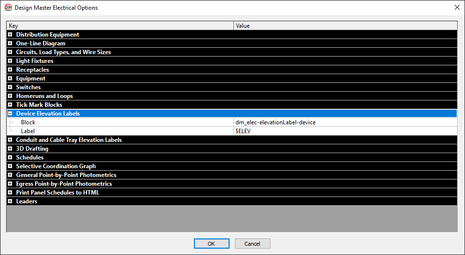
Device Elevation Labels
-
Block The block used for the elevation label when the Insert Device Elevation Label command is used.
-
Label The text that is used to display the elevation in the label. $ELEV is replaced with the elevation.
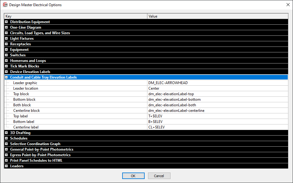
Conduit and Cable Tray Elevation Labels
-
Leader graphic The block that is used for elevation label leaders.
-
Leader location ▾ Where the leader points on the conduit or cable tray.
- Edge The leader points to the edge of the conduit or cable tray as shown below.
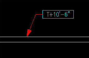
- Center The leader points to the center of the conduit or cable tray as shown below.
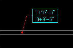
- Edge The leader points to the edge of the conduit or cable tray as shown below.
-
Top block The block used for the elevation label when the Insert Top Elevation Label command is used.
-
Bottom block The block used for the elevation label when the Insert Bottom Elevation Label command is used.
-
Both block The block used for the elevation label when the Insert Top and Bottom Elevation Label command is used.
-
Centerline block The block used for the elevation label when the Insert Centerline Elevation Label command is used.
-
Top label The text that is used to display the top elevation in the label. $ELEV is replaced with the elevation.
-
Bottom label The text that is used to display the top elevation in the label. $ELEV is replaced with the elevation.
-
Centerline label The text that is used to display the top elevation in the label. $ELEV is replaced with the elevation.
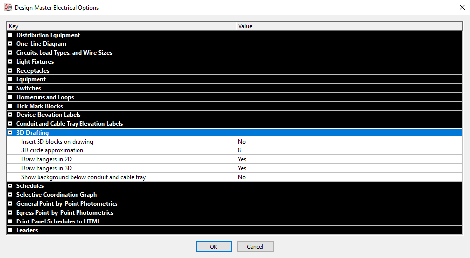
3D Drafting
-
Insert 3D blocks on drawing ▾ Whether a 3D block is inserted when a 2D block is inserted.
This setting has no impact on the 3D-BIM export commands.
warningIf you do not want to see the blocks, select No. Do not freeze or turn off the layer using AutoCAD commands. If the 3D layer is frozen or turned off, devices will no longer copy properly.
-
3D circle approximation Circles are approximated in the 3D model as polygons. This option sets the number of sides of a polygon used to represent a circle. Higher numbers more closely approximate a circle, but greatly increase file size. The minimum number value for this option is 8.
-
Draw hangers in 2D ▾ Whether hangers are drawn in 2D.
-
Draw hangers in 3D ▾ Whether hangers are drawn in 3D. This setting has no impact on the 3D-BIM export commands. It only affects whether they are visible in AutoCAD.
-
Show background below conduit and cable tray ▾ Whether the architectural background that appears behind conduits and cable trays is visible.
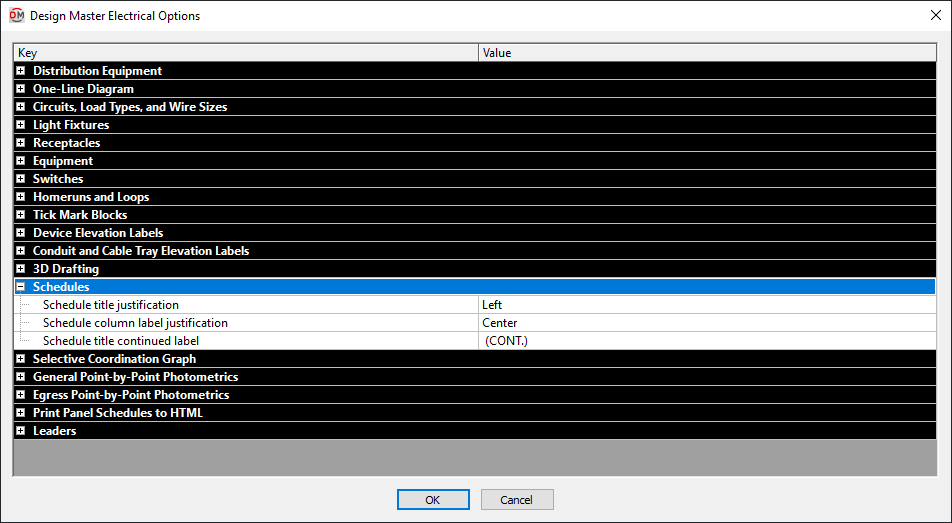
Schedules
-
Schedule title justification ▾ The justification for the title at the top of all of the schedules.
- Left The schedule title is justified to the left.
- Center The schedule title is centered.
-
Schedule column label justification ▾ The justification for the label at the top of each column in all of the schedules.
- Left The column labels are justified to the left.
- Center The column labels are centered.
-
Schedule title continued label The text in this option is added to the schedule title when the schedule is broken into multiple sections.
When inserting schedules, there is an option to set a maximum height for the schedule. If the schedule exceeds this height, the schedule is continued in a second section next to the first. The title of the second and following sections is the schedule title plus the text in the Schedule title continued label option.
Selective Coordination Graph
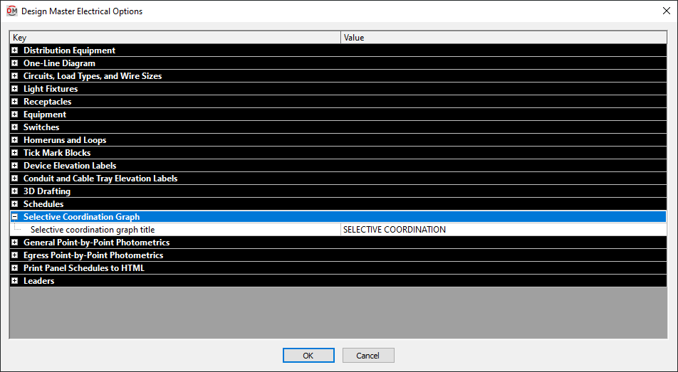
- Selective coordination graph title The default text that is entered in the Title field when running the Insert Selective Coordination Graph command.
General Point-by-Point Photometrics
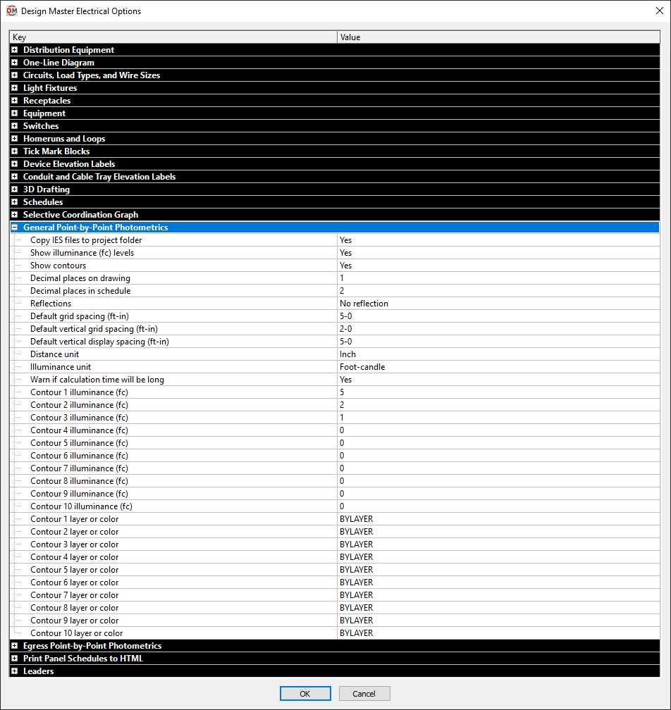 Most of these options set the default values that appear when running the Calculate General Photometrics command. These values can be changed in the Calculate General Photometrics dialog box.
-
Copy IES files to project folder ▾ Whether IES files loaded into the Light Fixture Project Schedule are copied to the project folder.
-
Default grid spacing The default Grid Spacing value that will be used when creating a new general photometric calculation area or line. This value can be changed when the area or line is created.
-
Default vertical grid spacing The default Vertical Calculation Spacing value that will be used when creating a new general photometric calculation area or line. This value can be changed when the area or line is created.
-
Default vertical display spacing The default Vertical Display Spacing value that will be used when creating a new general photometric calculation area or line. This value can be changed when the area or line is created.
-
Warn if calculation time will be long ▾ Whether a warning will be displayed before calculating general photometrics for an area with a high number of calculation points or solids.
Egress Point-by-Point Photometrics
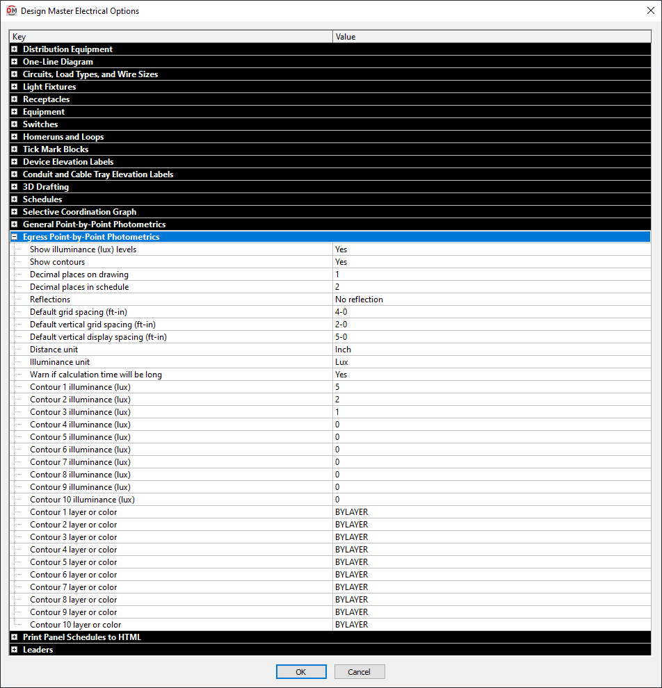
Most of these options set the default values that appear when running the Calculate Egress Photometrics command. These values can be changed in the Calculate Egress Photometrics dialog box.
-
Default grid spacing The default Grid Spacing value that will be used when creating a new egress photometric calculation area or line. This value can be changed when the area or line is created.
-
Default vertical grid spacing The default Vertical Calculation Spacing value that will be used when creating a new egress photometric calculation area or line. This value can be changed when the area or line is created.
-
Default vertical display spacing The default Vertical Display Spacing value that will be used when creating a new egress photometric calculation area or line. This value can be changed when the area or line is created.
-
Warn if calculation time will be long ▾ Whether a warning will be displayed before calculating egress photometrics for an area with a high number of calculation points or solids.
Print Panel Schedules to HTML
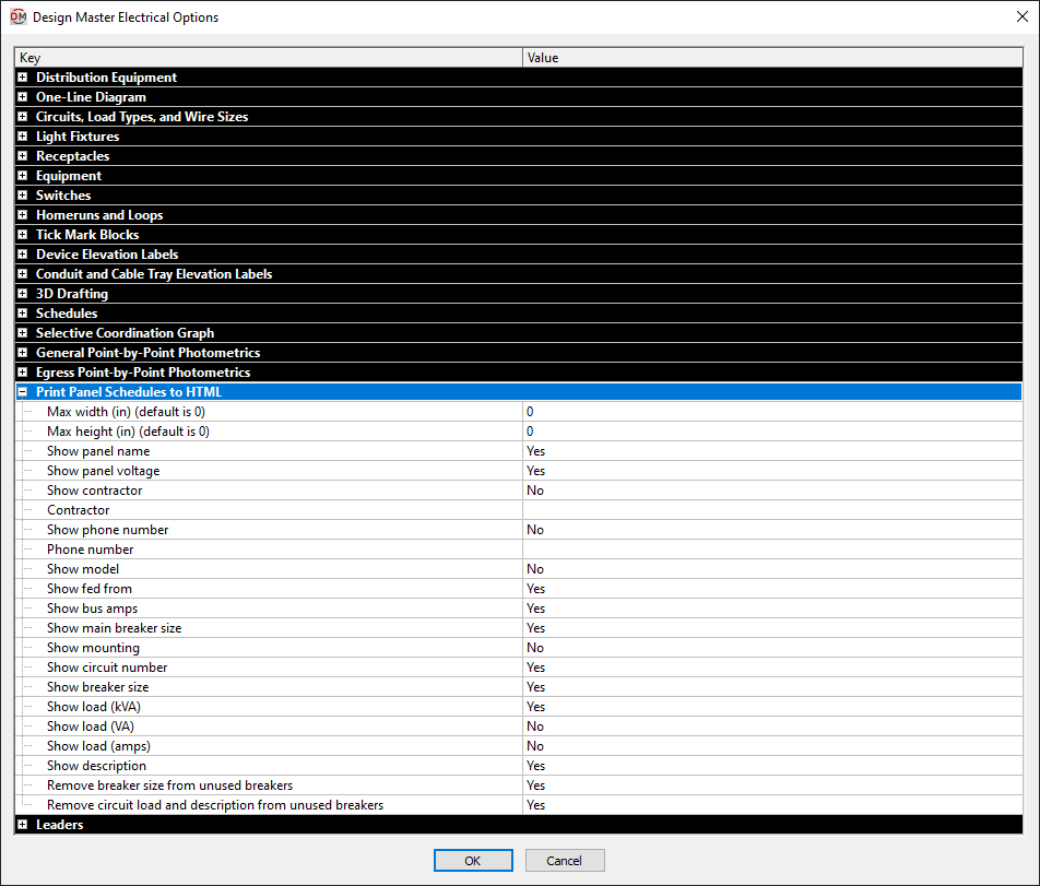
These options set the default values and settings that appear when running the Print Distribution Equipment Schedule command. These values can be changed in the Print Panel Schedule to HTML dialog box.
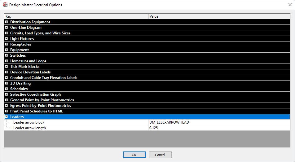
Leaders
-
Leader arrow block The block used for leader arrowheads.
-
Leader arrow length The length of the leader arrowhead.