Wire Sizing
The
Visit the General Customization Commands section for more information about how the
To customize the wire sizing tables in the current project, go to
Ribbon: ![]() Wire Sizing
Wire Sizing
Pulldown Menu:
To customize the master wire sizing tables, go to
Ribbon: ![]() Wire Sizing
Wire Sizing
Pulldown Menu:
Wire Sizing Dialog Box
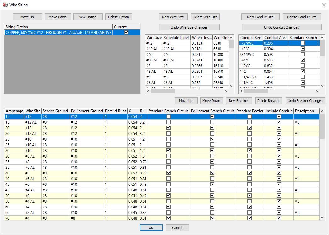
The Wire Sizing dialog box consists of four sections:
-
The top-left section is used to specify the sizing options. Each sizing option controls which conduit sizes and breaker sizes are used by default when sizing feeders and branch circuits in your project.
-
The top-middle section is used to specify the wire sizes available.
-
The top-right section is used to specify the conduit sizes available. The sizing option controls whether each conduit size is used when sizing feeders and branch circuits automatically.
-
The bottom section is used to specify the breaker and feeder sizes available. The sizing option controls whether each breaker size is used when sizing feeders and branch circuits automatically.
Sizing Option
This section of the dialog box provides a list of all of the sizing options. Each sizing option controls what is used when sizing wires automatically.
In the Conduit Size section, which ☐ Standard Branch and ☐ Standard Feeder boxes are checked is based upon the active sizing option.
In the Breakers and Conductors section, which ☐ Standard Branch Circuit, ☐ Equipment Branch Circuit, and ☐ Standard Feeder boxes are checked is based upon the active sizing option.
-
Press this button to move the selected row up in the Sizing Option ☰ list.
-
Press this button to move the selected row down in the Sizing Option ☰ list.
-
Press this button to create a new sizing option. The New Wire Sizing Option dialog box will open.

-
New Wire Sizing Option Name: The name of the new sizing option.
-
Copy Sizing Information from this Option ☰ The sizing option from which to copy settings. This sets the starting values for the columns controlled by the sizing option.
-
-
Press this button is delete the selected sizing option.
-
Sizing Option ☰ The name of the sizing option.
This value can be displayed at the bottom of the feeder schedule inserted on the drawing. Visit the Insert Feeder Schedule section for more information.
The default wire sizing table uses copper conductors, rigid steel conduit, and references NEC Table 310.16: 60°C #12 through #1, 75°C 1/0 and above.
-
☐ Current The sizing option that is active in the project. Branch circuit and feeder sizes are chosen based upon the settings of the selected sizing option. Only one sizing option can be active in a project at a time.
Wire Size
This section of the dialog box provides a list of all of the wire sizes.
-
Press this button to create a new wire size. The new row will be added to the bottom of the list when it is created. When you close and reopen the dialog box, the size will be sorted to the correct location in the list based upon the wire area.
-
Press this button to delete the selected wire size.
-
Press this button to revert the wire size settings to their values when the dialog box was opened.
-
Wire Size The name of the wire size. This label is shown in the wire callout and in fields where the wire size can be selected.
-
Schedule Label The label for the wire size when it is shown in a schedule. The wire size can be shown in the panel schedule, fault schedule, and voltage drop schedule.
-
Wire + Insulation Area The area of the wire with insulation in square inches. Visit NEC Table 5 and NEC Table 5A. Used to calculate the conduit fill.
-
Wire Only Area The area of the wire itself in circular mils.
-
Group The type of material for the wire size. If the ground wire is upsized, it will be upsized to the next wire size in the same Group.
Conduit Size
This section of the dialog box provides a list of all of the conduit sizes.
-
Press this button to create a new conduit size. The new row will be added to the bottom of the list when it is created. When you close and reopen the dialog box, the size will be sorted to the correct location in the list based upon the conduit area.
-
Press this button to delete the selected conduit.
-
Press this button to revert the conduit settings to their values when the dialog box was opened.
-
Conduit Size The name of the conduit size. The conduit size is included at the front of wire callouts that include conduit. This label is shown in fields where the conduit size can be selected.
-
Conduit Area The area of the conduit in square inches. Visit NEC Table 4. Used to calculate the conduit fill. Conduits are sized automatically so that the maximum fill is 40%, as specified in NEC Table 1.
-
☐ Standard Branch Whether the conduit size is used when automatically sizing branch circuits.
-
☐ Standard Feeder Whether the conduit size is used when automatically sizing feeders.
Breakers & Conductors
This section of the dialog box provides a list of the breaker sizes and corresponding conductors.
This list can contain multiple breakers of the same size. For each breaker size, one breaker can be set as the default used when sizing branch circuits and feeders automatically. Other breakers of that size can be chosen when sizing them manually.
-
Press this button to move the selected row up in the list. Breaker sizes can be moved within breakers of the same size. Breakers cannot be moved out of numerical order.
-
Press this button to move the selected row down in the list. Breaker sizes can be moved within breakers of the same size. Breakers cannot be moved out of numerical order.
-
Press this button to add a new breaker. The new row will use the same settings as the selected row when the button was pressed.
-
Press this button to delete the selected breaker.
-
Press this button to revert the breaker settings to their values when the dialog box was opened.
-
Amperage The breaker size.
-
Wire Size ▾ The size of the phase wires for the breaker. The values in this field are based upon the Wire Size section of the dialog box.
-
Service Ground ▾ The size of the service ground for the breaker. This size should be selected based upon NEC Table 250.102(C)(1).
This wire size is used for the ground when the distribution equipment is connected to the utility or to a transformer. The values in this field are based upon the Wire Size section of the dialog box.
-
Equipment Ground ▾ The size of the equipment ground for the breaker. This sizing should be selected based upon NEC Table 250.122.
This wire size is used for the ground when the distribution equipment is connected to anything except the utility or a transformer. The values in this field are based upon the Wire Size section of the dialog box.
-
Parallel Runs The number of parallel runs of conduit for the breaker. Each run contains the same size wires.
-
X The reactance of the wires. Visit NEC Table 9 for values.
warningThe reactance must be adjusted for the number of parallel runs.
-
R The resistance of the wires. Visit NEC Table 9 for values.
warningThe resistance must be adjusted for the number of parallel runs.
-
☐ Standard Branch Circuit Whether the breaker and wire sizes are used when automatically sizing branch circuits.
Only one breaker of each size can have this box checked. You do not need to have it checked for each size breaker. Breaker sizes that are not checked can still be selected manually.
tipBy default, spaces and spares will use the smallest breaker that has this box checked.
-
☐ Equipment Branch Circuit Whether the breaker and wire sizes are used when automatically sizing branch circuits based upon the MCA and MOCP of equipment connected to them.
Only one breaker of each size can have this box checked. You do not need to have it checked for each size breaker. Breaker sizes that are not checked can still be selected manually.
-
☐ Standard Feeder Whether the breaker and wire sizes are used when automatically sizing feeders to distribution equipment.
Only one breaker of each size can have this box checked. You do not need to have it checked for each size breaker. Breaker sizes that are not checked can still be selected manually.
-
☐ Include Conduit Whether the wire size label for this breaker includes the conduit size.
-
Description A label that is added after the Amperage when breakers are listed in other dialog boxes.
When manually selecting a breaker or conductors, the list will include all of the breaker and wire sizes. If there are two definitions of the same size breaker and wire, use this label to differentiate them so you can choose the correct breaker. This label is not displayed on the drawing.