Equipment
This section describes how to use equipment.
Equipment is used to model individual electrical connections that are typically not repeated in the design. Mechanical equipment and kitchen equipment are both examples of items that should be modeled as equipment.
Equipment can be inserted on the drawing or just exist in the database.
Common Equipment Information
The values that can be specified for equipment are listed below.
All of these values must be set for each piece of equipment. Unlike receptacles and light fixtures, values cannot be pulled from a schedule.
-
Group: ▾ The group that the piece of equipment is in. All of the equipment in a group are displayed in a single list. For more information about equipment groups, visit the Equipment Projects Groups section.
-
Equipment Callout: The name of the piece of equipment. The callout is used to label the equipment on the drawing and in the equipment list.
-
Panel Description: ▾ The value that is displayed in the circuit description for the circuit that the equipment is connected to.
- Same as Equipment Callout The circuit description on the panel schedule will be the equipment callout. This is the default setting.
- Custom Enter a custom description in the Custom Panel Description field provided. Custom descriptions are most useful when you need to shorten the label that is displayed on the panel schedule.
-
Circuit: The circuit to which the equipment is connected.
-
Total Connected Load (kVA): The sum of all of the connected loads on the piece of equipment in kVA.
-
Total Demand Load (kVA): The sum of all of the calculated loads on the piece of equipment in kVA.
-
Total Connected Load (Amps): The sum of all of the connected loads on the piece of equipment in amps. This load depends upon both the load in kVA and the voltage of the equipment connection.
-
Volts: ▾ The voltage for the piece of equipment.
-
☐ Ground Whether the equipment requires a ground wire.
-
☐ Isolated Ground Whether the equipment requires an isolated ground wire. If this is checked, an isolated ground wire is included in the wire callout for the branch circuit connected to this device.
-
Elevation: The elevation of the equipment connection. Visit the Elevation section for more information about entering this value.
-
Layer System: ▾ Visit the Layer System section for more information.
-
Drawing Note 1:, Drawing Note 2: These notes will be displayed on the drawing below the equipment callout.
Disconnect
-
Type: ▾ The type of equipment connection and disconnect. The graphics that are displayed for the equipment on the drawing are dependent upon the equipment type. The type also determines whether a separate disconnect graphic is shown.
The types available in this list can be modified using the Equipment Blocks command.
-
Trip: ▾ The trip size of the disconnect in amps.
-
Press this button to configure the curve for the disconnect. The Select Curve dialog box will open.
-
Elevation: ▾ The elevation of the disconnect. This elevation can be defined separately from the elevation of the equipment connection in cases where the elevations are different. Visit the Elevation section for more information about entering this value.
-
NEMA Rating: ▾ The NEMA rating of the disconnect. This value is displayed on the drawing as a note on the disconnect block.
tipIf you want to set the NEMA rating for the equipment schedule without showing it on the drawing, do not use this field. Instead, use one of the Schedule Note fields in the Schedule Information dialog box, then configure the Insert Equipment List command to display that note.
Breaker and Wire Sizing
-
FLA/ BCSC: The full load amps or branch circuit selection current. This value can be used to size the breaker according to NEC 430.52 and 440.22, depending upon the Breaker Size ▾ setting. It can also be used in Wire Size ▾ settings that specify it.
-
MCA: The minimum circuit amps. This value can be used to size the conductors to the equipment. It is not used in any of the calculations for the breaker size.
-
MOCP: The maximum overcurrent protection. This value can be used when sizing motor-compressor breakers.
-
Breaker Size: ▾ How the breaker for the equipment is sized.
- Motor-Compressor, <= MOCP (or loads if no MOCP) Breaker will be sized to match the MOCP. The FLA / BCSC value will be ignored. If no MOCP value is specified, the breaker is sized based upon the connected load of the device. Use this setting for NEC 440.22(C).
- Motor-Compressor, <= 175% of BCSC, <= MOCP Breaker will be sized to not exceed 175% of the FLA / BCSC value. The largest breaker that is less than 175% of the FLA / BCSC value will be used. If that is larger than the MOCP, the MOCP value will be used. Use this setting for NEC 440.22(A) and (C).
- Motor-Compressor, <= 225% of BCSC, <= MOCP Breaker will be sized to not exceed 225% of the FLA / BCSC value. The largest breaker that is less than 225% of the FLA / BCSC value will be used. If that is larger than the MOCP, the MOCP value will be used. Use this setting for NEC 440.22(A) Exception no. 2 and (C).
- Motor, Dual Element Fuse, <= 175% of FLA Breaker will be sized to not exceed 175% of the FLA / BCSC value. The largest breaker that is less than 175% of the FLA / BCSC value will be used. Use this setting for NEC 430.52 dual element fuses.
- Motor, Dual Element Fuse, <= 225% of FLA Breaker will be sized to not exceed 225% of the FLA / BCSC value. The largest breaker that is less than 225% of the FLA / BCSC value will be used. Use this setting for NEC 430.52(C)(1)(b)(2).
- Motor, Inverse Time Breaker, <= 250% of FLA Breaker will be sized to not exceed 250% of the FLA / BCSC value. The largest breaker that is less than 250% of the FLA / BCSC value will be used. Use this setting for NEC 430.52 inverse time breakers.
- Size based upon loads Breaker will be sized based upon the connected load of the device.
- Specific breaker size Breaker is set to the specific size chosen from the list.
-
Press this button to configure the curve for the breaker. The Select Curve dialog box will open.
-
Frame Size: ▾ How the frame for the equipment is sized.
- Same as Breaker Size Frame will use the same size as the Breaker Size ▾.
- Specific frame size Frame is set to the specific size chosen from the list.
-
Wire Size: ▾ How the conductors for the equipment are sized.
- Motor-Compressor, >= MCA (if no MCA, loads if motor, breaker if not) Conductors will be sized to be greater than the MCA. Use this setting for NEC 440.33 and 440.35. If no MCA value is specified, the conductors are sized based upon the connected load of the device.
- Single Motor-Compressor, >= 125% of BCSC Conductors will be sized to be greater than 125% of the FLA / BCSC value. Use this setting for NEC 440.32.
- <= MOCP Conductors will be sized to not exceed the MOCP.
- Size based upon loads Conductors will be sized based upon the connected load of the device.
- Size based upon breaker Conductors will be sized based upon the Breaker Size ▾.
- Specific breaker and wire size Conductors are sized to match the breaker and wire size chosen from the list.
Loads
-
Load 1, Load 2, Load 3, Load 4 An individual piece of equipment can have up to four separate assigned loads, each assigned a different ☐ Load Type. Visit the Load Information section for more information.
When the Horsepower ▾ field is set, the connected kVA for the load is calculated based upon NEC Tables 430.248 and 430.250. If the Connected field is later changed, the Horsepower ▾ field will reset to be blank.
-
Press this button to set the load on a piece of equipment in amps. The Set Load in Amps dialog box will open.

- Connected Load 1:, Connected Load 2:, Connected Load 3:, Connected Load 4: The current on each load in amps. Each field will be disabled if the corresponding load is disabled in the main equipment dialog box.
Enter the load in amps for each connected load and press the button. The load will be converted to kVA based upon the Volts ▾ setting for the equipment and transferred to the corresponding Connected field.
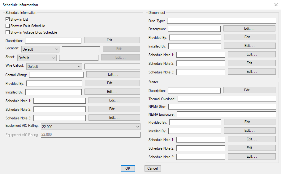
Schedule Information
Press the button to open the Schedule Information dialog box. This dialog box is used to set information about the equipment that is displayed on the schedule. These values are not displayed or used anywhere else. Any fields you do not plan to display on the schedule can be ignored.
- Press this button beside a field to enter a multiline note for the field.
-
☐ Show in List Whether the equipment is displayed in the list on the drawing. Visit the Insert Equipment List section for more information.
-
☐ Show in Fault Schedule Whether the equipment is displayed in the fault schedule. Visit the Insert Fault Schedule section for more information.
-
☐ Show in Voltage Drop Schedule Whether the equipment is displayed in the voltage drop schedule. Visit the Insert Voltage Drop Schedule section for more information.
-
Description: The description of the equipment.
-
Location: ▾ The location of the equipment.
- Default The name of the room where the equipment is inserted will be displayed on the schedule.
- Custom Enter the location in the field provided. This option is useful if you have not defined rooms in your project or want a location other than the room name displayed.
-
Sheet: ▾ The sheet on which the equipment is inserted.
- Default The name of the drawing file where the equipment is inserted will be displayed on the schedule.
- Custom Enter the sheet in the field provided.
-
Wire Callout: ▾ The callout of the branch circuit wire connected to the equipment.
- Default The callout from the circuit is displayed on the schedule.
- Custom Enter the wire callout in the field provided.
-
Control Wiring: Information about the control wiring for the equipment.
-
Provided By: Who is responsible for providing the equipment.
-
Installed By: Who is responsible for installing the equipment.
-
Schedule Note 1:, Schedule Note 2:, Schedule Note 3: These notes appear on the equipment schedule. Visit the Schedule Notes section for more information.
-
Equipment AIC Rating: ▾ The ampere interrupting capacity (AIC) rating for the device. This value is not automatically calculated. You must specify this value for all of the equipment in the project.
Disconnect
-
Fuse Type: The fuse type of the disconnect.
-
Description: The description of the disconnect.
-
Provided By: Who is responsible for providing the disconnect.
-
Installed By: Who is responsible for installing the disconnect.
-
Schedule Note 1:, Schedule Note 2:, Schedule Note 3: These notes appear on the equipment schedule to describe the disconnect. Visit the Schedule Notes section for more information.
Starter
-
Description: The description of the starter.
-
Thermal Overload: The thermal overload of the starter.
-
NEMA Size: The NEMA size of the starter.
-
NEMA Enclosure: The NEMA enclosure of the starter.
-
Provided By: Who is responsible for providing the starter.
-
Installed By: Who is responsible for installing the starter.
-
Schedule Note 1:, Schedule Note 2:, Schedule Note 3: These notes appear on the equipment schedule to describe the starter. Visit the Schedule Notes section for more information.
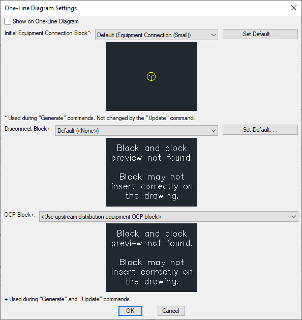
One-Line Diagram Settings
Press the button to open the One-Line Diagram Settings dialog box. This dialog box is used to set the blocks for the equipment when it is displayed on the one-line diagram.
-
☐ Show on One-Line Diagram Whether the equipment is displayed on the one-line diagram. Most equipment will not have this box checked. When this box is not checked, the equipment will not be available to be inserted on the one-line diagram.
-
Initial Equipment Connection Block: The block used on the drawing for the equipment. The button allows you to change the Default equipment connection block in the One-Line Diagram Options section.
-
Disconnect Block: The block used on the drawing for the disconnect. The button allows you to change the Default equipment disconnect block in the One-Line Diagram Options section.
-
OCP Block: The block used on the drawing for the OCP.
- <Use upstream distribution equipment OCP block> The equipment OCP will use the same OCP block as the upstream distribution equipment.
Commands
📄️ Create Equipment
To create equipment to place on the drawing or save in the project database, go to
📄️ Query or Edit Multiple Equipment
To modify a piece of equipment that has been inserted on the drawing or in the database, go to
📄️ Circuit Equipment in Database
To circuit equipment in the database, go to
📄️ Insert Equipment on this Drawing
The Insert Equipment on this Drawing command is used to insert equipment on the drawing that exists in the database but not on a drawing. Equipment that exists only in the database can be created using the Create Equipment command, the Remove Equipment from this Drawing command, and the Import Equipment from Another Project command.
📄️ Copy Equipment in Database
The Copy Equipment in Database command is used to copy equipment in the database.
📄️ Remove Equipment from this Drawing
The Remove Equipment from this Drawing command is used to remove equipment from a drawing while leaving it in the database.
📄️ Delete Equipment from Database
The Delete Equipment from Database command is used to delete equipment that is in the database but not on a drawing.
📄️ Insert or Move Equipment Callout
To insert or move a callout for an equipment on the drawing, go to
📄️ Modify Equipment Callout
To change the information displayed in an equipment callout on the drawing, go to
📄️ Remove Equipment Callout
To remove an equipment callout on the drawing, go to
📄️ Find Equipment on Drawing
To find a piece of equipment located on the current drawing, go to
📄️ Import Equipment from Another Project
The Import Equipment from Another Project command is used to copy equipment created in another project to the current project. This command is useful when you want to reuse an equipment schedule from a previous project.
📄️ Insert Equipment List
The Insert Equipment List command is used to insert a list of equipment on the drawing. The list will include all of the equipment from a single group in the project. Separate lists can be inserted for each group.
📄️ Equipment Project Groups
Equipment groups are used to categorize different types of equipment. Each group has a separate list that can be inserted on the drawing. These lists can have different formats to display different information for the different types of equipment.
📄️ Equipment Standards Groups
Settings for equipment groups can be created and stored in the standards database. These settings can be copied to new projects when they are created.