Distribution Equipment
This section describes how to create and manage distribution equipment. "Distribution equipment" is a term we use to refer to all of the electrical distribution devices that may appear in your project except for devices on branch circuits.
Distribution Equipment Dialog Box Settings
Distribution equipment is created and modified using the distribution equipment dialog box. The dialog box will display different fields and buttons dependent upon the type of equipment, but typically contains the settings described in the sections below.
General Settings
These settings are used to specify values related to load, voltage, connection type, and more. The information below applies to all distribution equipment unless otherwise indicated.
-
Callout: The name of the equipment.
-
Connected Load: The connected load on the equipment in kVA and in amps.
-
Calculated Load: The calculated load on the equipment, including all of the diversity factors, in kVA and in amps.
-
Volts: ▾ The voltage, number of poles, and number of wires for the equipment. The list includes typical North American voltages, as well as high leg, international, and medium voltages. Does not apply to low voltage panels, transformers and UPSs.
The Volts ▾ field can be changed directly when the distribution equipment has no upstream or downstream connections. If the equipment is connected to another equipment, another equipment is connected to it, or any branch circuit devices are connected, the Volts ▾ field cannot be changed directly. Instead, press the button to change the Volts ▾ of the equipment. This button is required to properly handle anything that is already connected. Visit the Changing the Voltage of Distribution Equipment section for more information.
-
Primary/Input Volts / Secondary/Output Volts: ▾ The primary or input voltage and secondary or output voltage of the equipment, as well as the number of poles and number of wires. The list includes typical North American voltages, as well as high leg, international, and medium voltages. Applies to transformers and UPSs. If the transformer or UPS is connected to another equipment, press the button to change this setting. Visit the Changing the Voltage of Distribution Equipment section for more information.
For transformers, the Primary Volts ▾ and Secondary Volts ▾ settings must have the same number of phases.
For UPSs, the Input Volts ▾ and Output Volts ▾ settings can be different phases.
-
Bus Amps: ▾ The size of the bus in amps. Applies to panels, switchboards, bus gutters/bus ducts, motor control centers, and meter centers.
Motor control centers have two settings: Horizontal Bus Amps ▾ and Vertical Bus Amps ▾.
-
Main Disconnect Type: ▾ The type of disconnect for the equipment. The graphics on the bus on the one-line diagram are controlled by this field. Applies to panels, switchboards, motor control centers, and meter centers.
- Main Lugs Only The bus bar on the one-line diagram does not have a disconnect.
- Breaker The bus bar on the one-line diagram includes a breaker graphic.
- Fused Switch The bus bar on the one-line diagram includes a fused switch graphic.
-
Trip: ▾ The trip size of the main disconnect breaker or fused switch in amps. This value cannot be set if Main Disconnect Type ▾ is set to Main Lugs Only. Applies to panels, switchboards, motor control centers, and meter centers.
-
Frame: ▾ The frame size of the main disconnect breaker or fused switch in amps. This value cannot be set if Main Disconnect Type ▾ is set to Main Lugs Only. Applies to panels, switchboards, motor control centers, and meter centers.
-
Press this button to configure the curve for the main disconnect breaker or fused switch. The Select Curve dialog box will open. This button is disabled if Main Disconnect Type ▾ is set to Main Lugs Only. Applies to panels, switchboards, motor control centers, and meter centers.
-
Mounting: ▾ How the equipment is mounted. The value of this setting can be displayed on the distribution equipment schedule. It is for informational purposes only and is not otherwise used. Does not apply to transformers, enclosed breakers/disconnects, or low voltage panels.
-
Neutral: ▾ The size of the distribution equipment neutral. The value of this setting can be displayed on the distribution equipment schedule. It is for informational purposes only and is not otherwise used. Applies to panels, switchboards, UPSs, transfer switches, and meter centers.
-
Number of <Connection Types>: How many connection locations are available on this equipment.
The label on this field depends upon the equipment type. The possible labels include Number of Poles, Number of Positions, Number of Lugs, Number of Taps, Number of Starters, and Number of Breakers.
-
Starting <Connection Type>: The number used for numbering the connection type listed.
The default starting value is 1. In some cases, you may need to start the numbering at a different point. For example, on a two-section panel that is treated like an 84-circuit panel, the circuits are numbered from 1 to 42 and 43 to 84. On the second panel, you would set the Starting Circuit to 43.
The label on this field depends upon the equipment type. The possible labels include Starting Circuit, Starting Position, Starting Lug, Starting Tap, Starting Starter, and Starting Breaker.
-
Lugs: ▾ The lugs available on the equipment. This setting controls the type of connection you can make and the graphics displayed on the bus bar on the one-line diagram. Applies to panels, switchboards, enclosed breakers/disconnects, transfer switches, and meter centers.
- STANDARD One set of lugs at the top of the bus.
- DOUBLE Double lugs located at the top of the bus. Enables the 🔘 Top Lugs option when connecting other equipment to this equipment.
- FEEDTHRU Lugs located at the top and bottom of the bus. Enables the 🔘 Feedthrough option when connecting other equipment to this equipment.
-
☐ IG Bus Whether the equipment contains an isolated ground bus. The value of this setting can be displayed on the distribution equipment schedule. It is for informational purposes only and is not otherwise used. Applies to panels, switchboards, UPSs, transfer switches, and meter centers.
-
Layer System: ▾ Visit the Layer System section for more information.
Changing the Voltage of Distribution Equipment
When a distribution equipment is first created, you change the voltage using the Volts ▾ field. When the equipment is connected to another equipment or any branch circuit devices, the Volts ▾ field cannot be changed directly. Instead, press the button to change the Volts ▾ of the equipment. This button is required to properly handle anything that is already connected.
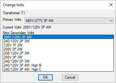
When you press the button, the Change Volts dialog box will open.

-
Primary Volts: ▾ The primary voltage supplied to the transformer or UPS. Does not apply to other distribution equipment.
-
Current Volts: The current voltage supplied to the distribution equipment.
-
New Volts / New Secondary Volts ☰ A list of the current and possible voltages for the equipment. The listed voltages are the ones that share at least one circuit voltage in common.
For transformers, the Primary Volts ▾ and New Secondary Volts ☰ settings for transformers must have the same number of phases. For UPSs, the phases can be different.
Select the desired new voltage and press the button. The Design Master Electrical dialog box shown below will appear.

When the voltage on the distribution equipment is changed, any connected branch circuit devices will be checked for consistency. Devices that cannot be connected to the newly selected voltage will be uncircuited.
All upstream and downstream distribution equipment connected to the selected equipment will be disconnected. These connections must be reestablished using the Connect Distribution Equipment in Database or Connect Distribution Equipment on One-Line Diagram command.
Group Settings
The settings in the Group section are used to assign the equipment to a schedule group and adjust group settings. The information below applies to all distribution equipment.
-
Opens the Schedule Groups dialog box.
-
Opens a list of available groups the equipment can be moved to.
-
Opens a list of available groups the equipment can be copied to. You can set a new callout for the copy.
Fault Analysis Settings
The settings in the Fault Analysis section are used to specify values related to fault calculation analysis. The information below applies to all distribution equipment unless otherwise indicated, with the following exceptions:
- For low voltage panels, this section is not available.
- For generators, only the button is available.
- For recurring panel templates, only the button and Panel AIC Rating ▾ field are available.
To manually specify a value, check the box next to it unless otherwise indicated. Use this when you know the value of a specific item or want to override what is calculated for you.
-
Feeder Length: The length of the conductor feeding the equipment. The value is automatically calculated if the equipment and its upstream equipment are inserted on the drawing.
The label on this field depends upon the equipment type. The possible labels include Feeder Length, Primary Length, and Normal Feeder Length.
-
Bypass Feeder Length / Emergency Feeder Length: The length of the second conductor feeding a UPS or a transfer switch. The Normal Feeder Length corresponds to the equipment connected to the Normal Feeder in the Feeder Specification section. This feeder length corresponds to the equipment connected to the Bypass Feeder. The value is automatically calculated if the equipment and its upstream equipment are inserted on the drawing.
-
Impedance %: The impedance through a transformer as a percentage. The higher the impedance, the lower the fault current on the secondary of the transformer. Applies only to transformers.
Manually enter this value if you know what it should be. It can typically be obtained from the transformer manufacturer.
If you do not know the value, a default based upon the KVA ▾ of the transformer is used:
Transformer kVA Default Transformer Impedance % 0 - 100 1.75% 112.5 - 300 2% 500 2.5% 750+ 5.75% -
X/R Ratio: The X/R Ratio of the transformer. Applies only to transformers.
Manually enter this value if you know what it should be. It can typically be obtained from the transformer manufacturer.
A default value of 5 is used if you do not enter a value.
-
Press this button to set the fault at the device in amps. This button is disabled if the box to the right is unchecked.
The label on this field depends upon the device type. The possible labels include , , , and .
For transformers, the fault can be set at the primary and at the secondary.
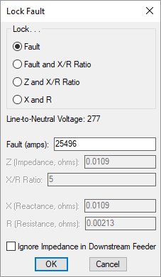
Check the box next to this button to open the Lock Fault dialog box. Use this dialog box to specify the fault value at the equipment, based upon the information that you know.
-
🔘 Lock. . . The values you can set vary depending upon the setting of this field. The other values are calculated based upon the ones you have locked.
- Fault Specify the Fault at the equipment. An X/R Ratio of 5 is used. Use this when you know the Fault but not the X/R Ratio of the equipment. This setting is the most common choice.
- Fault and X/R Ratio Specify the Fault at the equipment and the X/R Ratio. Use this when you know the Fault and X/R Ratio of the equipment.
- Z and X/R Ratio Specify the Z (impedance) and X/R Ratio.
- X and R Specify the X (reactance) and R (resistance).
-
Line-to-Neutral Voltage: The line-to-neutral voltage of the equipment. This voltage is used in the fault calculations.
-
Fault: The fault at the equipment.
-
Z: The impedance of the equipment.
-
X/R Ratio: The X/R ratio of the equipment.
-
X: The reactance of the equipment.
-
R: The resistance of the equipment.
-
☐ Ignore Impedance in Downstream Feeder Whether the impedance in the downstream feeder is ignored. The fault at the downstream equipment will be the same as the fault at this equipment. This setting is required by plan reviewers in some jurisdictions.
-
-
Total Fault: The fault at the device, taking into account the fault from the utility and any motors in the project.
-
Press this button to recalculate the Total Fault value.
-
<Device Type> AIC Rating: ▾ The ampere interrupting capacity (AIC) rating for the device. This value is not automatically calculated. You must specify this value for all of the equipment in the project.
The label on this field depends upon the device type. The possible labels include Panel AIC Rating ▾, Secondary Breaker AIC Rating ▾, Device Tap AIC Rating ▾, Tap AIC Rating ▾, Bypass Breaker AIC Rating ▾, MCC AIC Rating ▾, TS AIC Rating ▾, and AIC Rating ▾.
Feeder Length Settings
-
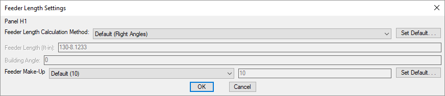
Press this button to open the Feeder Length Settings dialog box. Use this dialog box to specify how the feeder length is calculated.
-
Feeder Length Calculation Method: ▾ Sets how the feeder length is calculated. The other values you can set vary depending upon the setting of this field.
- Default The default calculation method for the project. The button allows you to change the Feeder length calculation method ▾ setting in the Distribution Equipment options section.
- Right Angles The feeder length is calculated using line segments at right angles to one another. The direction of the segments is determined by the Building Angle.
- Straight Line The feeder length is calculated using a straight line.
- Custom Enter a value for the feeder length.
-
Feeder Length: The calculated length of the feeder in feet and inches. This value can be set manually when the Feeder Length Calculation Method ▾ is set to Custom.
-
Building Angle: Sets the building angle relative to the alignment point orientation when Feeder Length Calculation Method ▾ is set to Right Angles. Visit the How Building Angle Affects Calculations article in the knowledge base for more information about this setting.
-
Feeder Make-Up: ▾ The extra length of wire included in the feeder length to account for the wire used for distribution equipment connections. It is used in the fault calculation, voltage drop calculation, and takeoffs. The button allows you to change the Feeder make-up setting in the Distribution Equipment options section.
-
Default distribution equipment AIC: Sets the default value for the AIC Rating ▾ field.
Feeder length calculation method: Sets the default for the Feeder Length Calculation Method ▾ field.
Building angle: Sets the default value for the Building Angle field.
Feeder make-up: Sets the default value for the Feeder Make-Up ▾ field. This option can be further customized with the Ignore make-up on feeders shorter than this option.
Feeder Specification Settings
The settings in the Feeder Specification section are used to configure the upstream feeder to the equipment. The information below applies to all distribution equipment except generators and low voltage panels unless otherwise indicated.
UPSs and transfer switches have a Normal Feeder Specification section and a Bypass Feeder Specification section. These sections correspond to the two feeders to these types of equipment. They work the same as the Feeder Specification section.
-
Fed From: The equipment that this equipment is connected to. It is the equipment upstream from this equipment that is closer to the utility.
-
☐ Description in Upstream Device: The description used in the distribution equipment schedule where this equipment is connected. By default, this field uses the equipment type and the equipment name. To override this value, check the box and enter a new description.
-
Upstream OCP / Primary OCP: ▾ The trip size of the overcurrent protection (OCP) in the device upstream of the distribution equipment.
- Same as Main Disconnect or Bus Amps If the Main Disconnect Type ▾ is set to Breaker or Fused Switch, the OCP is sized to match the Trip ▾ field. If the Main Disconnect Type ▾ is set to Main Lugs Only, the OCP is sized to match the Bus Amps ▾ field.
- Size to Match kVA The OCP is sized to match the KVA ▾ field. Applies to transformers and UPSs.
- Same as TS Amps The OCP is sized to match the Size ▾ field. Applies to transfer twitches.
- Lugs or N/A There is no OCP for this equipment. No breaker size is listed in the upstream panel. The feeder is sized based upon the Same as Main Disconnect or Bus Amps setting.
- Specific breaker size The OCP is set to the specific size chosen from the list.
-
Press this button to configure the curve for the upstream OCP. The Select Curve dialog box will open. If Upstream OCP ▾ is set to Size to Match kVA or Lugs or N/A, this button is disabled.
-
Frame Amps: ▾ The frame size of the OCP in the device upstream of the distribution equipment.
- Same as Main Disconnect or Bus Amps If the Main Disconnect Type ▾ is set to Breaker or Fused Switch, the frame is sized to match the Trip ▾ field. If the Main Disconnect Type ▾ is set to Main Lugs Only, the frame is sized to match the Bus Amps ▾ field.
- Size to Match kVA The frame is sized to match the KVA ▾ field. Applies to transformers and UPSs.
- Same as TS Amps The frame is sized to match the Size ▾ field. Applies to transfer twitches.
- None There is no frame for this equipment. No frame size is listed in the upstream panel.
- Specific frame size The frame is set to the specific size chosen from the list.
-
Conductor Amps: ▾ Sets the size of the hot wires in the feeder.
- Size Automatically The hot wires are sized based upon the Upstream OCP ▾ field.
- Specific breaker and wire size The hot wires are sized to match the breaker and wire size chosen from the list.
-
Neutral: ▾ Sets the size of the neutral wire in the feeder.
- Same as Phase The neutral wire is the same size as the hot wires specified in the Conductor Amps ▾ field.
- Double Phase The neutral wire uses two wires that are each the size of the hot wires specified in the Conductor Amps ▾ field.
- None No neutral wire is included in the feeder.
- Specific wire size The neutral wire is sized to match the wire size chosen from the list.
-
Ground: ▾ Sets the size of the ground wire in the feeder.
- NEC 250.122 The ground wire is sized based upon the Equipment Ground ▾ setting for the breaker and wire size specified in the Conductor Amps ▾ field. Visit the Wire Sizing command for more information.
- NEC 250.102 The ground wire is sized based upon the Service Ground ▾ setting for the breaker and wire size specified in the Conductor Amps ▾ field. Visit the Wire Sizing command for more information.
- None No ground wire is included in the feeder.
- Specific wire size The ground wire is sized to match the wire size chosen from the list.
-
☐ IG Conductor Whether the feeder includes an isolated ground.
-
Conduit Size: ▾ Sets the size of the conduit for the feeder. The conduit fill percentage is displayed next to the Conduit Size ▾ field. Changing the conduit size will update the fill percentage.
- Size Automatically The conduit is sized automatically based upon the wires in the feeder. All conduits are sized using a 40% conduit fill per NEC Table 1.
- None No conduit is included for the feeder.
- Specific conduit size The conduit is sized to match the conduit size chosen from the list.
-
Size: The callout for the feeder listing the chosen conduit and wire sizes. This callout can be displayed on various schedules and on the one-line diagram.
Feeder and Service Calculation Settings
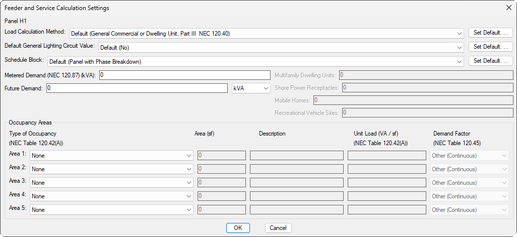
Press the button to open the Feeder and Service Calculation Settings dialog box. This dialog box is used to manage how loads are calculated for the selected distribution equipment. The chosen calculation method impacts how the various load types assigned to devices are used to determine the calculated load. Visit the Feeder and Service Calculations article in the knowledge base for more information about how to correctly set the load types, occupancy areas, and demand factors for each load calculation method.
-
Load Calculation Method: ▾ How the service load is calculated, depending upon the type of structure. The button allows you to change the Default load calculation method ▾ setting in the Distribution Equipment options section.
- General Commercial or Dwelling Unit, Part III Use NEC 120 Part III.
- New Restaurant, All Electric Use the first column in NEC 120.88.
- New Restaurant, Not All Electric Use the second column in NEC 120.88.
- School Use NEC 120.86.
- Dwelling Unit Use NEC 120.82.
- Dwelling Unit, Existing Use NEC 120.83.
- Multifamily Dwelling (Single units use Part III) Use NEC 120.84 and NEC 120.85. If the distribution equipment serves a single dwelling unit, the calculation uses NEC 120 Part III. The Multifamily Dwelling Units field sets the number of dwelling units used to calculate the diversity. The number of dwelling units on a panel will include the total number on downstream equipment.
- Multifamily Dwelling (Single units use Part IV) Use NEC 120.84 and NEC 120.85. If the distribution equipment serves a single dwelling unit, the calculation uses NEC 120.82. The Multifamily Dwelling Units field sets the number of dwelling units used to calculate the diversity. The number of dwelling units on a panel will include the total number on downstream equipment.
- Multifamily Dwelling (Single units use Existing) Use NEC 120.84 and NEC 120.85. If the distribution equipment serves a single dwelling unit, the calculation uses NEC 120.83. The Multifamily Dwelling Units field sets the number of dwelling units used to calculate the diversity. The number of dwelling units on a panel will include the total number on downstream equipment.
- Marina Use NEC 120 Part III. Use NEC 120.120 for the Marina / Mobile Home / RV load type. The Shore Power Receptacles field sets the number of shore power receptacles used to calculate the diversity.
- Marina with Sub-Meters Use NEC 120 Part III. Use NEC Table 120.120 Note 2 for the Marina / Mobile Home / RV load type. The Shore Power Receptacles field sets the number of shore power receptacles used to calculate the diversity.
- Mobile Home Park Use NEC 120 Part III. Use NEC 120.141 for the Marina / Mobile Home / RV load type. The Mobile Homes field sets the number of mobile homes used to calculate the diversity.
- RV Park Use NEC 120 Part III. Use NEC 120.130 for the Marina / Mobile Home / RV load type. The Recreational Vehicle Sites field sets the number of sites used to calculate the diversity.
- None (Dynamic footer will be blank) Use NEC 120 Part III. When the schedule is inserted on the drawing, load calculations will not be displayed in the footer.
-
Default General Lighting Circuit Value: ▾ Whether circuits connected to the distribution equipment are automatically designated as General Lighting Circuits as defined in the NEC. General lighting circuits are ignored when calculating loads. Typically, this is set to No. The button allows you to change the Default general lighting circuit value ▾ setting in the Distribution Equipment options section.
-
Schedule Block: ▾ The schedule block for the distribution equipment. The button will open the Set Default Schedule Block dialog box. This dialog box allows you to set a default schedule block for the distribution equipment type. Select a schedule block from the available list and press the button.
-
Metered Demand: The current load for an existing building.
-
Future Demand: The anticipated load for future work. Can be entered in kVA or as a percentage of the calculated load.
Occupancy Areas
The Occupancy Areas section is used to calculate the demand for occupancy areas on the selected distribution equipment.
-
Type of Occupancy ▾ The type of occupancy area. The available types are defined in NEC Table 120.42(A). The Description and Unit Load are based upon the selected type. Select Custom to enter these values manually.
-
Area The size of the occupancy area in square feet.
-
Description The description of the occupancy area.
-
Unit Load The unit load for the occupancy area. The unit load is based upon the type of occupancy as defined in NEC Table 120.42(A).
-
Demand Factor ▾ The demand factor for the occupancy area.
- Other (Continuous) The demand factor is based upon the All others row of NEC Table 120.45. The lighting will be calculated as a continuous load with a 125% multiplier applied.
- Other (Noncontinuous) The demand factor is based upon the All others row of NEC Table 120.45.The lighting will be calculated as a noncontinuous load with a 100% multiplier applied.
- Dwelling Unit The demand factor is based upon the Dwelling units row of NEC Table 120.45.
- Hospital The demand factor is based upon the Hospitals row of NEC Table 120.42 (NEC 2017 and earlier). This demand factor should not be used for areas where the entire lighting is likely to be used at one time, as in operating rooms or dining rooms.
- Hotel or Motel The demand factor is based upon the Hotels and motels, including apartment houses without provision for cooking by tenants row of NEC Table 120.45. This demand factor should not be used for areas where the entire lighting is likely to be used at one time, as in ballrooms or dining rooms.
-
Warehouse (Storage) The demand factor is based upon the Warehouses (storage) row of NEC Table 120.45.
Default load calculation method: Sets the default for the Load Calculation Method ▾ field.
Default general lighting circuit value: Sets the default for the Default General Lighting Circuit Value ▾ field.
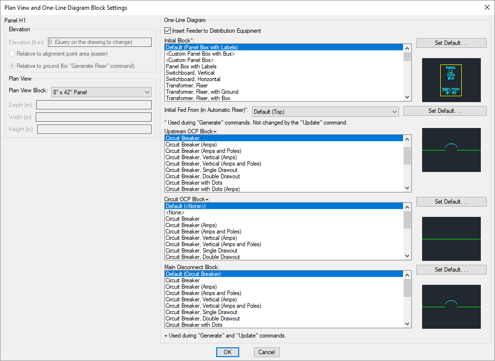
Plan View and One-Line Diagram Block Settings
Press the button to open the Plan View and One-Line Diagram Block Settings dialog box. This dialog box is used to manage the blocks that represent the distribution equipment on the floor plan and one-line diagram. The information listed below is applicable to all distribution equipment except generators and low voltage panels unless otherwise indicated.
- Elevation The elevation of the distribution equipment. Visit the Elevation section for more information.
Plan View
-
☐ Select Block Based upon kVA Whether the Plan View Block ▾ is automatically set based upon the kVA setting. Applies to transformers only.
-
Plan View Block: ▾ The block used for the distribution equipment on the drawing. This list is based upon the settings in the Distribution Equipment Plan View Blocks command.
If the Plan View Block ▾ is set to a block with Custom Size ▾ set to Yes in the Distribution Equipment Plan View Blocks dialog box, the Depth, Width, and Height fields can be used to set the size of the equipment in inches.If the selected block has Custom Size ▾ set to No, these fields are disabled.
-
Depth: ▾ The size of the equipment in the direction, perpendicular to the rotation angle of the block.
-
Width: ▾ The size of the device in the direction, parallel to the rotation angle of the block.
-
Height: ▾ The size of the device in the direction.
One-Line Diagram
This section sets the blocks used for the distribution equipment and its connections on the one-line diagram. The button allows you to change the default for each block in the One-Line Diagram section.
-
☐ Insert Feeder to Distribution Equipment Whether the upstream feeder for the distribution equipment is included on the one-line diagram.
-
Initial Block: ☰ The block used for the distribution equipment itself when it is inserted using the Generate One-Line or Generate Riser command. Changing this setting does not affect blocks already on the one-line diagram.
-
Initial Fed From: ▾ Whether the feeder is drawn to the top or bottom of the block when it is inserted using the Generate Riser command. Changing this setting does not affect blocks already on the one-line diagram.
-
Upstream OCP Block: ☰ The block for the upstream OCP. Changing this setting will affect blocks already on the one-line diagram.
- <Use upstream distribution equipment OCP block> uses the same OCP block as the upstream distribution equipment.
-
Upstream OCP Block 2: ☰ The block for the second upstream OCP. Applies to transfer switches and UPSs only.
-
Circuit OCP Block: ☰ The block for the downstream OCP. Changing this setting will affect blocks already on the one-line diagram.
-
Main Disconnect Block: ☰ The block for the main disconnect. Only available if Initial Block ☰ is set to <Custom Panel Box with Bus> and Main Disconnect Type ▾ is set to Breaker or Fused Switch. Does not apply to transformers, transfer switches, or UPSs.
Elevation input: Sets whether the elevation is measured from the alignment point or the ground by default.
Schedule and Length Settings
Press the button to open the Schedule and Length Settings dialog box. This dialog box is used to manage length calculation settings for the selected distribution equipment, as well as how or whether the distribution equipment is displayed in different schedules. The button allows you to change the project default for each field in the Options command.
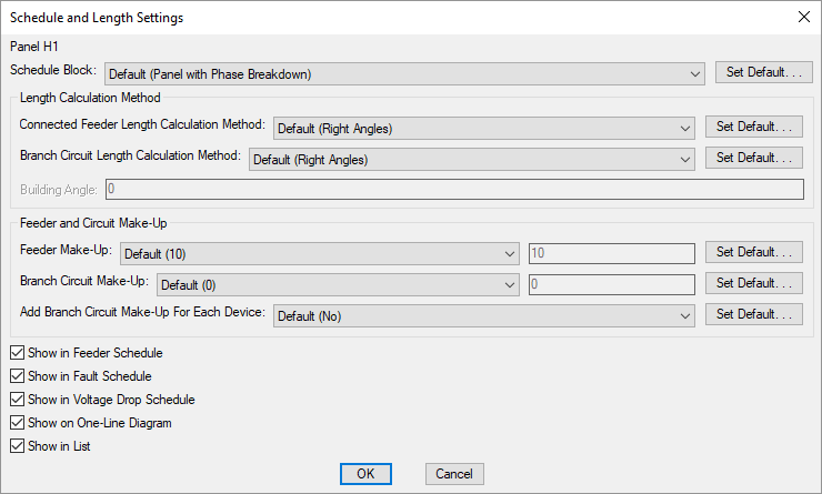
- Schedule Block: ▾ The block used for the distribution equipment schedule. This list is based upon the settings in the Distribution Equipment Schedule Blocks command.
Length Calculation Method
-
Connected Feeder Length Calculation Method: ▾ Sets the default feeder length calculation method when another distribution equipment is connected to this distribution equipment. Visit the Feeder Length Settings section for more information.
-
Branch Circuit Length Calculation Method: ▾ Sets the branch circuit length calculation method when measuring from this distribution equipment to a light fixture, receptacle, or other device.
Feeder and Circuit Make-Up
-
Feeder Make-Up: ▾ The extra length of wire included in the feeder length to account for the wire used for distribution equipment connections. It is used in the fault calculation, voltage drop calculation, and takeoffs.
-
Branch Circuit Make-Up: ▾ The extra length of wire included in branch circuit lengths to account for branch circuit connections. It is used in the fault calculation, voltage drop calculation, and takeoffs.
-
Add Branch Circuit Make-Up For Each Device: ▾ Whether the length specified in Branch Circuit Make-Up ▾ is added for each device on the circuit.
- Yes The make-up added to the branch circuit length is multiplied for each device on the circuit.
- No The make-up is only added to the branch circuit length once, regardless of the number of devices on the circuit.
-
☐ Show in Feeder Schedule Whether the upstream feeder for the distribution equipment is displayed in the feeder schedule.
-
☐ Show in Fault Schedule Whether the distribution equipment is displayed in the fault schedule.
-
☐ Show in Voltage Drop Schedule Whether the distribution equipment is displayed in the voltage drop schedule.
-
☐ Show in One-Line Diagram Whether the distribution equipment is displayed on the one-line diagram.
-
☐ Show in List Whether the distribution equipment is displayed in the list of distribution equipment of this type.
Feeder length calculation method: Sets the default for the Feeder Length Calculation Method ▾ field.
Circuit length calculation method: Sets the default for the Branch Circuit Length Calculation Method ▾ field.
Building angle: Sets the default value for the Building Angle field.
Feeder make-up: Sets the default value for the Feeder Make-Up ▾ field. This option can be further customized with the Ignore make-up on feeders shorter than this option.
Branch circuit make-up: Sets the default value for the Branch Circuit Make-Up ▾ field. This option can be further customized with the Add branch circuit make-up for each device ▾ option.
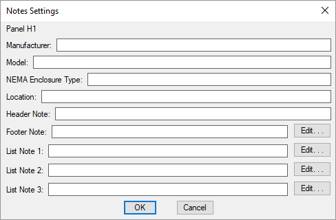
Notes Settings
Press the button to open the Notes Settings dialog box. This dialog box is used to manage notes for the selected distribution equipment. They are for informational purposes only and are not otherwise used.
-
Manufacturer: The manufacturer of the distribution equipment. This note can be displayed on the header of distribution equipment schedules, distribution equipment lists, and the one-line diagram.
-
Model: The model of the distribution equipment. This note can be displayed on the header of distribution equipment schedules, distribution equipment lists, and the one-line diagram.
-
NEMA Enclosure Type: The NEMA rating for the distribution equipment. This note can be displayed on the header of distribution equipment schedules, distribution equipment lists, and the one-line diagram.
-
Location: The location of the distribution equipment. In the default distribution equipment schedule blocks, this note is displayed in the header.
-
Header Note: A generic note field. In the default distribution equipment schedule blocks, this note is displayed in the header.
-
Footer Note: A generic note field. In the default distribution equipment schedule blocks, this note is displayed in the footer below the schedule. Press the button to enter a multiline note.
-
List Note 1: A generic note field that is displayed on distribution equipment lists only. It cannot be displayed on the distribution equipment schedule or one-line diagram. Press the button to enter a multiline note.
-
List Note 2: A generic note field that is displayed on distribution equipment lists only. It cannot be displayed on the distribution equipment schedule or one-line diagram. Press the button to enter a multiline note.
-
List Note 3: A generic note field that is displayed on distribution equipment lists only. It cannot be displayed on the distribution equipment schedule or one-line diagram. Press the button to enter a multiline note.
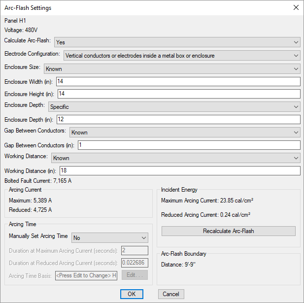
Arc-Flash Settings
Press the button to open the Arc-Flash Settings dialog box. This dialog box is used to manage the variables that affect arc-flash calculations for the selected distribution equipment.
-
Voltage: The voltage of the distribution equipment. The voltage determines the arc-flash calculation method that is used.
-
Calculate Arc-Flash: ▾ Whether arc-flash is calculated for the distribution equipment. Equipment that is not calculated will not be displayed in the arc-flash schedule on the drawing and will not have stickers created. The fields below will be disabled.
Because a sustained arc-flash is unlikely below 208V, equipment with voltages below 208V do not typically need arc-flash calculations performed and will have this field set to No by default.
-
Electrode Configuration: ▾ The electrode configuration as described in IEEE Std 1584-2018 Table 9. Horizontal configurations generally have higher incident energy than vertical configurations. Enclosed configurations generally have higher incident energy than open configurations. An enclosed configuration is recommended for most distribution equipment inside buildings. Visit the Electrode Configurations for Arc-Flash Calculations article in the knowledge base for more information about these configurations.
- Unknown This setting is recommended if the electrode configuration is unknown. The calculations provide conservative results.
- Vertical conductors or electrodes inside a metal box or enclosure This setting has the lowest incident energy among enclosed configurations.
- Vertical conductors or electrodes terminated in an insulating barrier inside a metal box or enclosure This setting has a lower incident energy than Horizontal conductors or electrodes inside a metal box or enclosure, but higher than Vertical conductors or electrodes inside a metal box or enclosure.
- Horizontal conductors or electrodes inside a metal box or enclosure This setting has the highest incident energy among all configurations.
- Vertical conductors or electrodes in open air This setting has the lowest incident energy among all configurations.
- Horizontal conductors or electrodes in open air This setting has the highest incident energy among open configurations.
-
Enclosure Size: ▾ The dimensions of the enclosure. The smaller the enclosure, the higher the incident energy. The size of the enclosure does not affect arcing current and arcing times.
-
Unknown This setting is recommended if the dimensions are unknown. The calculations will be based upon a 20" x 20" x 9" enclosure.
-
Known Enter values for the Enclosure Width and Enclosure Height fields and set Enclosure Depth ▾ manually. If possible, set the dimensions based upon the manufacturer's specifications. Typical enclosure dimensions are listed in IEEE Std 1584-2018 Table 8. Dimensions for equipment between 208V and 600V are listed in the table below.
Equipment Type Enclosure Size (HxWxD) Switchgear 20" x 20" x 20" MCC 14" x 12" x 8" Panel 14" x 12" x 8" Cable Junction Box 14" x 12" x 8"
-
-
Enclosure Height: The height of the enclosure.
-
Enclosure Width: The width of the enclosure.
-
Enclosure Depth: ▾ The depth of the enclosure.
- Typical The calculations will be based upon a depth greater than 8".
- Shallow The calculations will be based upon a depth of 8" or less.
- Specific Enter a value for the Enclosure Depth field manually.
-
Gap Between Conductors: ▾ The gap between the conductors. For devices between 208V and 600V, the most accurate calculation can be used when the gap between conductors is between 0.25" and 3". Within that range, the larger the gap, the higher the incident energy.
For gaps outside the 0.25" - 3" range, the calculations provide conservative results.
-
Unknown This setting is recommended if the gap is unknown. For devices between 208V and 600V, the calculations will be based upon a gap of 3". For devices above 600V, the calculations will be based upon a gap of 10".
-
Known Enter a value for the Gap Between Conductors manually. When possible, set the gap based upon the manufacturer’s specifications. Typical gaps between conductors are listed in IEEE Std 1584-2018 Table 8. Gaps for devices between 208V and 600V are listed in the table below.
Equipment Type Gap Between Conductors Switchgear 1.25" MCC 1" Panel 1" Cable Junction Box 0.5"
-
-
Working Distance: ▾ The distance from the possible arc point to the torso of the person working on the distribution equipment. The incident energy will be calculated at this distance from the equipment. The farther away from the equipment, the lower the incident energy. Any part of the body closer to the equipment than this distance will be exposed to higher incident energy than is calculated.
-
Unknown This setting is recommended if the working distance is unknown. The calculations will be based upon a working distance of 12".
-
Known Enter a value for the Working Distance manually. When possible, set the working distance based upon the actual dimensions of the equipment. Typical working distances are listed in IEEE Std 1584-2018 Table 10. Working distances for equipment between 208V and 600V are listed in the table below.
Equipment Type Working Distance Switchgear 24" MCC 18" Panel 18" Cable Junction Box 18"
-
-
Bolted Fault Current: The bolted fault current is the fault at the equipment. This value is calculated based upon the other settings in your project.
Arc-flash calculations assume the equipment and the fault are three-phase. For single-phase equipment, the calculations provide conservative results. If the fault is less than 500 A or greater than 106,000 A, the calculations provide conservative results.
-
Arcing Current, Maximum and Reduced: The predicted three-phase arcing current used to determine the operating time for the protective devices. The maximum arcing current is the upper limit for the equipment. The reduced arcing current is the lower limit for the equipment.
These values are calculated based upon the following ranges specified in IEEE Std 1584-2018:
- Voltage: 208V - 15,000V
- Bolted Fault Current: 500A - 106,000A @ 208V - 600V; 200A - 65,000A @ 600+V
- Gap Between Conductors: ▾ 0.25" - 3" @ 208V - 600V; 0.75" - 10" @ 600+V
If any of these values for the equipment are outside the listed range, the calculation will be performed using the Lee Method. If the Lee Method is used, only the Arcing Current, Maximum will be calculated.
-
Manually Set Arcing Time: ▾ Whether the arcing times are entered manually or set automatically based upon time-current curves set in the Select Curve dialog box.
- Yes Enter values for the arcing times and Arcing Time Basis field manually.
- No The arcing times and Arcing Time Basis field will be set automatically based upon the next protective device that is upstream of the equipment. If an upstream protective device has not been set, the arcing times will be set to 2 seconds and the Arcing Time Basis will display UNKNOWN BREAKER for the protective device.
-
Duration at Maximum Arcing Current and Reduced Arcing Current: The duration of the arc-flash at the Maximum Arcing Current and Reduced Arcing Current.
warningThe duration has a significant impact on the incident energy in seconds. The longer someone is exposed to the flash, the more intense the burn. The arcing time is based upon the time-current curve for the specific breaker you are using. These values are provided by the manufacturer and can typically be found on their website.
The incident energy is a function of the arcing current and the duration. Lower arcing currents that take longer to close the breaker can result in higher incident energy values than high arcing currents. To account for this, incident energy is calculated using both the Maximum Arcing Current and Reduced Arcing Current.
Fuses must be handled differently from breakers. The time-current curves for fuses may include both melting and clearing times. Use the clearing time if it is provided. If only the melting time is provided, you can approximate the clearing time by adding 10% to the melting time if it is greater than 0.3 seconds, or 15% if it is less than 0.3 seconds.
If the arcing current is above the total clearing time at the bottom of the curve (0.01 seconds), use 0.01 seconds.
-
Arcing Time Basis: The time-current curve the arcing times are based upon. The value of this setting can be displayed on the arc-flash schedule and one-line diagram. It is for informational purposes only and is not otherwise used.
-
Incident Energy, Maximum Arcing Current and Reduced Arcing Current: The total incident energy based upon the arcing current, arcing times, and working distance.
-
The Incident Energy and Arcing Time values are not updated as changes are made to this dialog box. Press this button to recalculate those values.
-
Arc-Flash Boundary Distance: The limited approach boundary for unprotected workers. At this distance, the harm inflicted upon an unprotected worker during an arc-flash incident will be limited to second-degree burns.
Insert on One-Line Diagram
Press the button to insert the active distribution equipment on the one-line diagram. The distribution equipment dialog box will close and the Insert Distribution Equipment command will run with the active distribution equipment selected.
If the selected distribution equipment is not connected to another device, after inserting it on the one-line diagram, you will be prompted to connect to an upstream distribution equipment that is closer to the utility.
Select upstream distribution equipment to connect to:
Select another device on the one-line diagram to proceed the same way as running the Connect Distribution Equipment on One-Line Diagram command, or press ENTER to finish the command without making a connection.
Insert on Plan View
Press the button to insert the active distribution equipment on the drawing. The distribution equipment dialog box will close and the Insert Plan View Block command will run with the active distribution equipment selected.
Commands
📄️ Querying Distribution Equipment
When the Query Device command is used on distribution equipment, it displays information related to the distribution equipment on the drawing. It does not display all of the information about the equipment.
📄️ Edit Distribution Equipment
To edit distribution equipment that has already been created, go to
📄️ Edit Multiple Distribution Equipment
For each distribution equipment type, there is an Edit Multiple command that is used to query or edit multiple distribution equipment of that type.
📄️ Connect Distribution Equipment in Database
The Connect Distribution Equipment in Database command is used to connect distribution equipment to each other without needing to insert them on the drawing.
📄️ Panels
To create or modify a panel, go to
📄️ Switchboards
To create or modify a switchboard, go to
📄️ Transformers
To create or modify a transformer, go to
📄️ Wireways
To create or modify a wireway, go to
📄️ Bus Gutters / Bus Ducts
To create or modify a bus gutter or bus duct, go to
📄️ Enclosed Breakers / Disconnects
To create or modify an enclosed breaker or disconnect, go to
📄️ Uninterruptible Power Supplies (UPS) / Phase Inverters
To create or modify an uninterruptible power supply (UPS) or phase inverter, go to
📄️ Motor Control Centers (MCC)
To create or modify a motor control center, go to
📄️ Meter Centers
To create or modify a meter center, go to
📄️ Generators
To create or modify a generator, go to
📄️ Transfer Switches
To create or modify a transfer switch, go to
📄️ Low Voltage Panels
To create or modify a low voltage panel, go to
📄️ Recurring Panel Templates
Recurring panel templates allow you to create multiple panels with the same settings. This can be useful when planning hotels, apartments, and other buildings in which multiple panels with the same specifications and connections will be used.
📄️ Create Recurring Panel Instance
To create a recurring panel instance, go to
📄️ Query or Edit Multiple Recurring Panel Instances
To query or edit multiple recurring panel instances, go to
📄️ Insert Recurring Panel Instance on this Drawing
To insert a recurring panel instance on a drawing, go to
📄️ Remove Recurring Panel Instance from this Drawing
To remove a recurring panel instance from a drawing, go to
📄️ Delete Recurring Panel Instance from Database
To delete a recurring panel instance from the project database, go to
📄️ Convert Panel to Recurring Panel Template
The Convert Panel to Recurring Panel Template command is used to create a recurring panel template from an existing panel. This can be useful when you need multiple panels with the same specifications and connections as a panel you have already created.
📄️ Insert Panel List
A list of panels in the current project can be inserted on the drawing.
📄️ Insert Switchboard List
A list of switchboards in the current project can be inserted on the drawing.
📄️ Insert Transformer List
A list of transformers in the current project can be inserted on the drawing.
📄️ Insert Wireway List
A list of wireways in the current project can be inserted on the drawing.
📄️ Insert Bus Gutter / Bus Duct List
A list of bus gutters and bus ducts in the current project can be inserted on the drawing.
📄️ Insert Enclosed Breaker / Disconnect List
A list of enclosed breakers and disconnects in the current project can be inserted on the drawing.
📄️ Insert UPS List
A list of UPSs and phase inverters in the current project can be inserted on the drawing.
📄️ Insert Motor Control Center List
A list of motor control centers in the current project can be inserted on the drawing.
📄️ Insert Meter Center List
A list of meter centers in the current project can be inserted on the drawing.
📄️ Insert Generator List
A list of generators in the current project can be inserted on the drawing.
📄️ Insert Transfer Switch List
A list of transfer switches in the current project can be inserted on the drawing.
📄️ Insert Low Voltage Panel List
A list of low voltage panels in the current project can be inserted on the drawing.
📄️ Insert Recurring Panel Template List
A list of recurring panel templates in the current project can be inserted on the drawing.
📄️ Insert Recurring Panel Instance List
A list of recurring panel instances in the current project can be inserted on the drawing.
📄️ Insert Plan View Block
The Insert Plan View Block command is used to locate distribution equipment on the drawing. The location is used to calculate the length of the feeders between distribution equipment. The feeder length is used in the fault current calculation, voltage drop calculation, and takeoffs.
📄️ Insert Plan View Blocks in Another Area or Drawing
The Insert Plan View Blocks in Another Area or Drawing command is used to place distribution equipment that is already inserted in an alignment point area into another alignment point area. The second alignment point area can be on the same or a different drawing.