Connect Distribution Equipment in Database
The
To connect distribution equipment in the database, go to
Ribbon: ![]() Connect Distribution Equipment in Database
Connect Distribution Equipment in Database
Pulldown Menu:
Distribution Equipment Connections Dialog Box
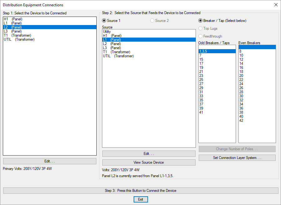
Step 1: Select the Device to be Connected (Downstream Device)
Select the device that is going to be connected from the list. This device will be the downstream distribution equipment that is further from the utility, also commonly called a sub-feed panel or a sub-panel.
Generators are not listed in this step. They cannot be connected to other equipment.
- Press this button to open the Distribution Equipment Dialog Box for the selected distribution equipment.
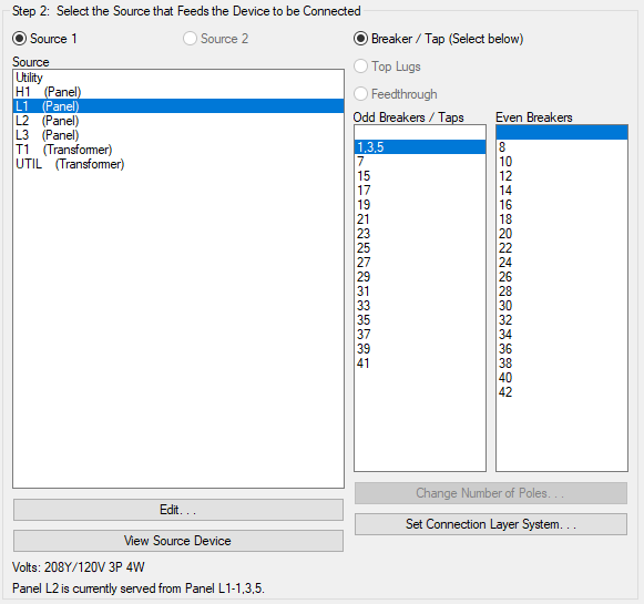
Step 2: Select the Source that Feeds the Device to be Connected (Upstream Device)
Select the device that the first device will be connected to from the list. This device will be the upstream distribution equipment that is closer to the utility.
-
🔘 Source 1 Make the connection for the first source of the downstream distribution equipment. Available for all distribution equipment types.
-
🔘 Source 2 Make the connection for the second source of the downstream distribution equipment. Available for UPSs and transfer switches.
-
Source ☰ The upstream distribution equipment that the downstream distribution equipment will be connected to.
The Utility selection at the top of the list is a special connection option. It is not a distribution equipment that is created by the user. It represents the utility connection that is beyond the definition of the project. Select this option for the utility transformer or any other device that is connected to the utility. You can also select this option to effectively disconnect devices from any upstream connections.
-
Press this button to open the Distribution Equipment Dialog Box for the selected distribution equipment.
-
Press this button to open the Panel View dialog box for the currently selected Source ☰ equipment. All of the breakers or taps for the panel and their descriptions will be displayed.
-
🔘 Top Lugs This selection is available for panels, switchboards, breakers, disconnects, and transfer switches that have their Lugs ▾ set to DOUBLE.
-
🔘 Feedthrough This selection is available for panels, switchboards, breakers, disconnects, and transfer switches that have their Lugs ▾ set to FEEDTHRU.
-
🔘 Breaker / Tap This selection is available for all equipment types. Select the breaker or tap to connect to using the Odd Breakers / Taps ☰ and Even Breakers ☰ lists.
-
Odd Breakers / Taps ☰ For panels, a list of the odd breakers. For all other distribution equipment, a list of all of the taps. The downstream equipment will be connected to the breaker or tap selected in this list.
The top blank entry will be selected for panels when an even breaker is used for the connection.
-
Even Breakers ☰ For panels, a list of the even breakers. Not used for all other distribution equipment. The downstream equipment will be connected to the breaker selected in this list.
The top blank entry will be selected for panels when an odd breaker is used for the connection.
-
Press this button to open the Change Number of Poles dialog box and change the number of poles for the currently selected circuit. This dialog box can be used to convert two-pole and three-pole circuits to multiple single-pole circuits. Visit the Change Number of Poles section for more information.
-
Press this button to change the layer system of the selected breaker or tap. Visit the Layer System section for more information.
Step 3: Connect the Device
After you have selected the two devices to connect and configured the source device connection, press the button to make the connection.