Insert Distribution Equipment
The
To insert distribution equipment or an equipment connection, go to
Ribbon: ![]() Insert Distribution Equipment
Insert Distribution Equipment
Pulldown Menu:
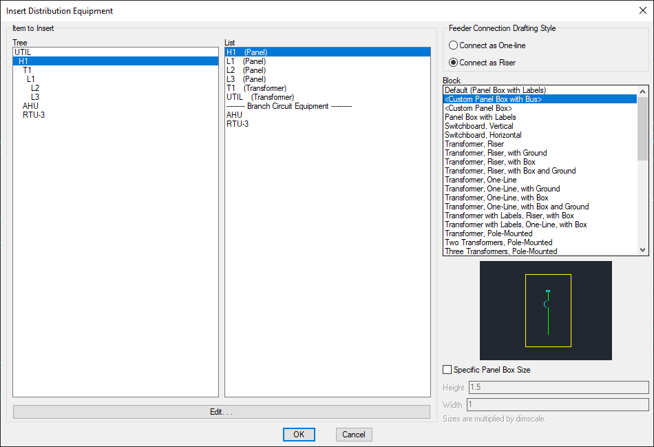
Insert Distribution Equipment Dialog Box
-
Tree / List ☰ The distribution equipment and equipment connections in the current project. They are listed in a tree corresponding to how the equipment are connected to each other, and alphabetically by callout.
tipBy default, distribution equipment will appear in this list, while equipment connections will not.
You can modify whether specific devices appear in this list using the Schedule and Length Settings dialog box for distribution equipment and the One-Line Diagram Settings dialog box for equipment connections.
-
🔘 Feeder Connection Drafting Style Whether feeders are connected to the selected block in a vertical one-line configuration or a horizontal riser configuration.
-
Block ☰ The block that will be used for the distribution equipment or equipment connection. More blocks can be added to this list using the One-Line Diagram Distribution Equipment Blocks→Edit Project List command. There are two special entries in the list:
- <Custom Panel Box with Bus> A box representing the panel with a bus bar inserted in the middle of it.
- <Custom Panel Box> A box representing the panel. No bus bar is inserted.
-
☐ Specific Panel Box Size If Custom Panel Box and Bus or Custom Panel Box is selected from the Block ☰ list, check this box to set the dimensions for the block.
-
Press this button to open the corresponding dialog box for the selected distribution equipment.
Press the button to insert the distribution equipment or equipment connection on the drawing.
Inserting a Panel Box
If Custom Panel Box and Bus or Custom Panel Box was selected from the Block ☰ list and ☐ Specific Panel Box Size was unchecked, you will be prompted to specify the location for the first corner of the panel box.
First corner of panel:
You will then be prompted for the second corner of the panel box.
Second corner:
If Custom Panel Box and Bus was selected, you will be prompted to specify the starting point of the bus bar or press ENTER to insert it in the default location.
The size of the panel block will affect the direction in which the bus will be inserted. The bus will be inserted in a direction matching the longest side of the box. A short, wide box will result in the bus being inserted horizontally. A tall, thin box will result in a vertical bus.
Feeders will be inserted between the distribution equipment or equipment connection and anything it is connected to that is already on the drawing.
Inserting a Distribution Equipment Diagram Block
If a different block was selected, or ☐ Specific Panel Box Size was checked, you will be prompted for the insertion point of the block.
Select insertion point:
If Custom Panel Box and Bus was selected, you will be prompted to specify the starting point of the bus bar or press ENTER to insert it in the default location.
The size of the panel block will affect the direction in which the bus will be inserted. The bus will be inserted in a direction matching the longest side of the box. A short, wide box will result in the bus being inserted horizontally. A tall, thin box will result in a vertical bus.
Feeders will be inserted between the distribution equipment or equipment connection and anything it is connected to that is already on the drawing.
Include vertical main breaker on horizontal panels: Sets whether the main breaker on horizontal panel blocks is inserted along the bus bar.
Default panel box height: Sets the default value for the Specific Panel Box Size Height field.
Default panel box width: Sets the default value for the Specific Panel Box Size Width field.
Default feeder connection layout: Sets the default for the Default Feeder Connection Layout setting.
There are several other options that affect the overall appearance of the one-line diagram. Visit the One-Line Diagram Options section for more information.