Insert Voltage Drop Schedule
The
To insert the voltage drop schedule, go to
Ribbon: ![]() Insert Voltage Drop Schedule
Insert Voltage Drop Schedule
Pulldown Menu:
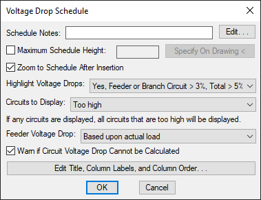
Voltage Drop Schedule Dialog Box
-
Schedule Notes: A note that will appear below the schedule when inserted on the drawing.
-
☐ Maximum Schedule Height: Whether the schedule has a maximum height. This height corresponds to inches on the printed page.
If this is not checked, the schedule will be in a single schedule.
If this is checked, you can specify the maximum height of the schedule. When the schedule exceeds this height, it will be continued in a second schedule next to the first. The label of the second schedule will have the Schedule title continued label option added to it to indicate that it is a continuation of the first schedule. Visit the Schedules options section for more information.
-
Press this button to specify the ☐ Maximum Schedule Height on the drawing. The dialog box will be closed and you will be prompted to specify the height.
Specify maximum schedule height:The distance that you enter on the drawing will be used as the maximum height. It is simplest to draw a line straight down to where the bottom of the schedule should be located.
-
☐ Zoom to Schedule After Insertion Whether the display will be moved to the schedule location after it has been inserted or updated. Check this box if you are having difficulty locating your schedule on a busy drawing.
-
Highlight Voltage Drops: ▾ Whether voltage drops that are too high are highlighted, and the threshold to be considered too high.
- Yes, Feeder or Branch Circuit > 3%, Total > 5% Feeder voltage drops that exceed 3%, branch circuit voltage drops that exceed 3%, and total voltage drops that exceed 5% will be highlighted. These values are based upon NEC 210.19 Informational Note and NEC 215.4(A)(2) Informational Note No. 2.
- Yes, Feeder > 2%, Branch Circuit > 3% Feeder voltage drops that exceed 2% and branch circuit voltage drops that exceed 3% will be highlighted.
- No Voltage drops that are too high will not be highlighted.
-
Circuits to Display: ▾ Which branch circuit voltage drops will be displayed for each distribution equipment.
- None No additional branch circuit voltage drops will be displayed.
- All All branch circuit voltage drops will be displayed.
- All with load All voltage drops for branch circuits with loads will be displayed.
- All with voltage drop > 0 All branch circuit voltage drops that exceed 0 will be displayed.
- All with homerun drawn All voltage drops for branch circuits with homeruns drawn will be displayed.
- Too high All voltage drops where the branch circuit voltage drop exceeds 3% or the total voltage drop exceeds 5% will be displayed.
For every setting except None, any branch circuit voltage drops that exceed 3% or total voltage drops that exceed 5% will also be displayed.
-
Feeder Voltage Drop: ▾ Whether voltage drop on feeders will be calculated based upon the actual load.
- Based upon actual load Voltage drop will be calculated based upon the loads specified for each piece of distribution equipment.
- Based upon 80% of panel capacity Voltage drop will be calculated based upon 80% of the capacity for each piece of distribution equipment.
-
☐ Warn if Circuit Voltage Drop Cannot be Calculated Whether you receive a warning if the branch circuit voltage drop cannot be calculated correctly due to circuiting errors.
If this is checked and any errors are found, an alert dialog box will open and the errors will be shown at the command line. The dialog box will also ask if you want to continue receiving this warning. Press the button to keep this setting checked the next time the Voltage Drop Schedule dialog box is opened. Press the button to uncheck this setting.
-
Press this button to modify the layout of the schedule on the drawing. Visit the Edit Voltage Drop Schedule List section for more information.
Inserting or Updating the Schedule on the Drawing
To insert or update the schedule, press the button.
Inserting the Schedule the First Time
If the schedule is not currently inserted on the drawing, you will be prompted for the insertion location of the schedule.
Specify insertion point for schedule:
The location you specify will be used as the top-left corner for the schedule.
Updating the Schedule Already on the Drawing
If the schedule is already inserted on the drawing, it will be updated in its current location.
You must update the schedule on the drawing when changes are made to the project schedule. The schedule will not update automatically.
The schedule will also be updated when the Update All Schedules and One-Line Diagram command is run.
If additional graphics, such as revision clouds, have been inserted over the schedule graphic, be sure to check their location after updating the schedule.
Errors
If there are errors in the distribution equipment definitions, an alert dialog box will open and the errors will be shown at the command line. Visit the Addressing Distribution Equipment Errors section for more information about fixing these errors.
Voltage Drop Schedule: Highlight voltage drops: Sets the default for the Highlight Voltage Drops ▾ field.
Voltage Drop Schedule: Circuits to display: Sets the default for the Circuits to Display ▾ field.
Voltage Drop Schedule: Warn if branch circuit voltage drop cannot be calculated: Sets whether the ☐ Warn if Circuit Voltage Drop Cannot be Calculated box is checked by default.
Voltage drop and transformers: Sets how voltage drop is calculated through transformers.
Calculate voltage drop based upon 80% of panel capacity: Sets the default for the Feeder Voltage Drop setting.
Feeder make-up: Sets additional length to be added to feeders for connections. This option can be further customized with the Ignore make-up on feeders shorter than this option.
Branch circuit make-up: Sets additional length to be added to branch circuits for connections. This option can be further customized with the Add branch circuit make-up for each device ▾ option.
Schedule title justification: Sets the justification for the schedule title.
Schedule column label justification: Sets the justification for column headings.
Schedule title continued label: Sets the label added to the schedule title for continued sections.