Instance Edit

Allows you to edit information about specific family instances in your project.
If nothing is selected, you will be prompted to select a family instance to edit.
If one or more pieces of electrical equipment are selected, the Panel Edit dialog box will open with the selected electrical equipment active.
If one or more family instances are selected, or after you select a family instance, one of the Instance Edit dialog boxes described below will appear, depending upon how the Device Type ▾ of the active instance's family has been configured in the Family Edit command.
Branch Circuit Device: Other / Equipment Connection
When the active family instance has Device Type set to Branch circuit device: Other, Branch circuit device: Equipment connection, or has not been configured using the Family Edit command, the Instance Edit dialog box below will appear.
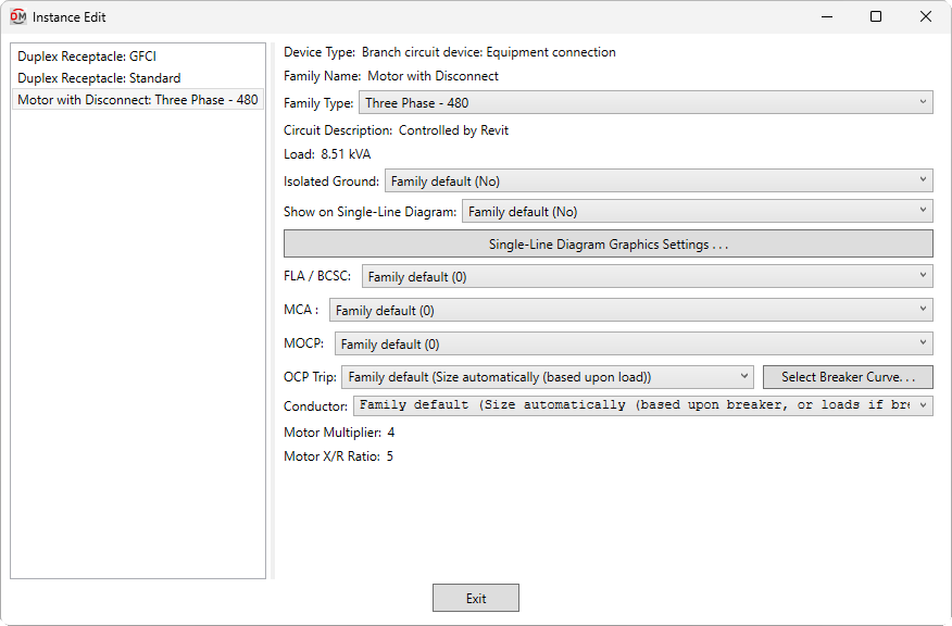
If the family instance has been configured using the Family Edit command, many of the fields in this dialog box will include a Family default setting. Fields with this setting will use the same setting as the corresponding field in the family.
-
List ☰ All of the instances that were selected when the command was run.
You can select multiple instances in the list using the SHIFT or CTRL key. Only fields shared by all of the selected instances will be shown. Fields that have different values across the selected instances will display <Varies>.
-
Device Type: The Device Type ▾ set for the family in the Family Edit command.
-
Family Name: The name of the Revit family for the instance.
-
Family Type: ▾ The type of the Revit family for the instance. The types in the list are based upon the instance Family Name.
-
Circuit Description: ▾ The circuit description for the instance.
- Family default Use the circuit description set for the family in the Family Edit command. If one has not been set, the Load Name will be used.
- Set circuit description in instance Enter a circuit description in the field provided.
- Based on parameter The value for the specified parameter will be used. Press the button to select a parameter. Visit the Using Non-ElectroBIM Parameters for ElectroBIM Settings article in the knowledge base for more information.
warningIf Circuit description method ▾ in the Project Options command is set to Use Revit circuit descriptions, the circuit description set in the family or instance will not be used. This field will display Controlled by Revit and will be disabled.
-
Load: The load of the instance as set in Revit.
-
Isolated Ground: ▾ Whether the branch circuit requires an isolated ground wire.
- Yes An isolated ground wire will be included in the wire callout for the branch circuit connected to the instance.
- No An isolated ground wire will not be included.
- Based on parameter The value for the specified parameter will be used. Press the button to select a parameter. Visit the Using Non-ElectroBIM Parameters for ElectroBIM Settings article in the knowledge base for more information.
-
Show on Single-Line Diagram: ▾ Whether the device is inserted on the single-line diagram when using the Generate One-Line, Generate Riser, or Export to AutoCAD commands, and whether it is displayed in the Insert Link and Copy Link commands. The default setting for branch circuit devices is No.
- Based on parameter The value for the specified parameter will be used. Press the button to select a parameter. Visit the Using Non-ElectroBIM Parameters for ElectroBIM Settings article in the knowledge base for more information.
-
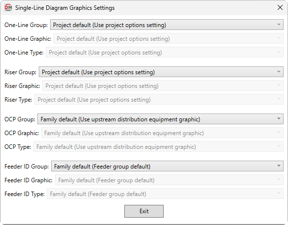
Press this button to open the Single-Line Diagram Graphics Settings dialog box. Use this dialog box to manage the graphics that represent the distribution equipment on the single-line diagram.
-
One-Line Group: ▾ The graphic category used for the device when it is inserted on a one-line diagram. The groups available are based upon settings in the Single-Line Diagram Device Graphics command.
- Family default The One-Line Group ▾ specified in the family will be used.
- Use project options setting The Default branch circuit device group ▾ specified in the Generate One-Line Project Options will be used.
-
One-Line Graphic: ▾ The graphic family used for the device. The values in this list are based upon the Single-Line Diagram Device Graphics command and the selected One-Line Group ▾.
-
One-Line Type: ▾ The graphic type used for the selected One-Line Graphic ▾.
-
Riser Group: ▾ The graphic category used for the device when it is inserted on a riser diagram. The groups available are based upon settings in the Single-Line Diagram Device Graphics command.
- Family default The Riser Group ▾ specified in the family will be used.
- Use project options setting The Default branch circuit device group ▾ specified in the Generate Riser Project Options will be used.
-
Riser Graphic: ▾ The graphic family used for the device. The values in this list are based upon the Single-Line Diagram Device Graphics command and the selected Riser Group ▾.
-
Riser Type: ▾ The graphic type used for the selected Riser Graphic ▾.
-
OCP Group: ▾ The graphic category used for the upstream OCP when the instance is inserted on the single-line diagram. The groups available are based upon settings in the Single-Line Diagram Feeder Graphics command.
- Family default The OCP Group ▾ specified in the family will be used.
- Use upstream distribution equipment graphic The Downstream OCP Group ▾ and Default Downstream OCP Graphic ▾ set in the upstream distribution equipment will be used.
- None No OCP graphic will be inserted.
-
OCP Graphic: ▾ The graphic family used for the upstream OCP. The values in this list are based upon the Single-Line Diagram Feeder Graphics command and the selected OCP Group ▾.
-
OCP Type: ▾ The graphic type used for the selected OCP Graphic ▾.
-
Feeder ID Group: ▾ The graphic category used for the feeder ID when the instance is inserted on the single-line diagram. The groups available are based upon settings in the Single-Line Diagram Feeder Graphics command.
- Family default The Feeder ID Group ▾ specified in the family will be used.
- Feeder group default The Feeder ID Graphic and Feeder ID Type set for the feeder ID's group in the Project Feeder ID Schedule will be used.
- None No feeder ID graphic will be inserted.
-
Feeder ID Graphic: ▾ The graphic family used for the feeder ID. The values in this list are based upon the Single-Line Diagram Feeder Graphics command and the selected Feeder ID Group ▾.
-
Feeder ID Type: ▾ The graphic type used for the selected Feeder ID Graphic ▾.
-
-
FLA / BCSC: ▾ The full load amps (FLA) or branch circuit selection current (BCSC).
- N/A The default value. The instance does not have an FLA or BCSC.
- Based on parameter The value for the specified parameter will be used. Press the button to select a parameter. Visit the Using Non-ElectroBIM Parameters for ElectroBIM Settings article in the knowledge base for more information.
- Custom Specify the value for the FLA or BCSC in the field provided.
-
MCA: ▾ The minimum circuit amps (MCA).
- N/A The default value. The instance does not have an MCA.
- Based on parameter The value for the specified parameter will be used. Press the button to select a parameter. Visit the Using Non-ElectroBIM Parameters for ElectroBIM Settings article in the knowledge base for more information.
- Custom Specify the value for the MCA in the field provided.
-
MOCP: ▾ The maximum overcurrent protection (MOCP).
- N/A The default value. The device does not have an MOCP.
- Based on parameter The value for the specified parameter will be used. Press the button to select a parameter. Visit the Using Non-ElectroBIM Parameters for ElectroBIM Settings article in the knowledge base for more information.
- Custom Specify the value for the MOCP in the field provided.
-
OCP Trip: ▾ How to size the breaker for the branch circuit to which the instance is connected.
- Size automatically (based upon load) The breaker is sized based upon 125% of the connected load. FLA / BCSC ▾, MCA ▾, and MOCP ▾ are all ignored.
- Motor-compressor, <= MOCP The breaker is sized to be less than the MOCP ▾ per NEC 440.22(C).
- Motor-compressor, <= 175% of BCSC, <= MOCP The breaker is sized to be less than 175% of the BCSC ▾ and less than the MOCP ▾ per NEC 440.22(A) & (C).
- Motor-compressor, <= 225% of BCSC, <= MOCP The breaker is sized to be less than 225% of the BCSC ▾ and less than the MOCP ▾ per NEC 440.22(A) Exception no. 2 & (C).
- Motor, dual element fuse, <= 175% of FLA The breaker is sized to be less than 175% of the FLA ▾ per NEC 430.52.
- Motor, dual element fuse, <= 225% of FLA The breaker is sized to be less than 225% of the FLA ▾ per NEC 430.52(C)(1)(b)(2).
- Motor, inverse time breaker, <= 250% of FLA The breaker is sized to be less than 250% of the FLA ▾ per NEC 430.52.
- Based on parameter The value for the specified parameter will be used. Press the button to select a parameter. Visit the Using Non-ElectroBIM Parameters for ElectroBIM Settings article in the knowledge base for more information.
- Specific ampacity The breaker size is set to the specific size chosen from the list.
-
Press this button to configure the curve for the breaker. The OCP Device Settings dialog box will open.
-
Conductor: ▾ How to size the conductors for the branch circuit to which the instance is connected.
- Size automatically (based upon breaker, or loads if breaker based upon motor) The conductors are sized automatically. The conductors are sized to match the breaker, or match the load if OCP Trip ▾ is set to one of the Motor choices.
- Multimotor, >= MCA The conductors are sized to be greater than the MCA ▾ per NEC 440.35.
- Motor-compressor, >= 100% of BCSC + 25% of max BCSC The conductors are sized to be greater than 100% of the combined BCSC ▾, plus 25% of the largest BCSC ▾ on the circuit per NEC 440.32 & 33.
- Size based upon loads The conductors are sized based upon 125% of the connected load.
- Size based upon breaker The conductors are sized based upon the breaker size.
- Based on parameter The value for the specified parameter will be used. Press the button to select a parameter. Visit the Using Non-ElectroBIM Parameters for ElectroBIM Settings article in the knowledge base for more information.
- Specific ampacity The wire size is set to the specific size chosen from the list.
-
Motor Multiplier: The multiplier used in fault calculations set in the Family Edit command. This field is only displayed if Device Type is set to Branch circuit device: Equipment connection.
-
Motor X/R Ratio: The X/R ratio used in fault calculations set in the Family Edit command. This field is only displayed if Device Type is set to Branch circuit device: Equipment connection.
Default OCP group / graphic / type: Sets the project defaults for the OCP Group ▾, OCP Graphic ▾, and OCP Type ▾ fields.
(One-line) Default branch circuit device group / graphic / type: Sets the project defaults for the One-Line Group ▾, One-Line Graphic ▾, and One-Line Type ▾ fields.
(Riser) Default branch circuit device group / graphic / type: Sets the project defaults for the Riser Group ▾, Riser Graphic ▾, and Riser Type ▾ fields.
Distribution Equipment
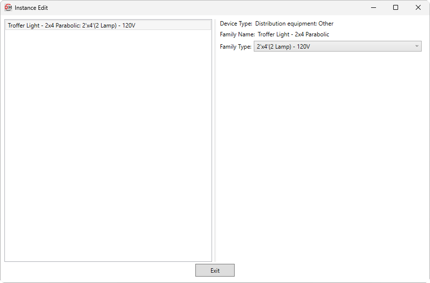
When the selected family instance is not a piece of electrical equipment and has Device Type set to Distribution equipment: Other, Distribution equipment: Panel, or Distribution equipment: Transformer, the Instance Edit dialog box below will appear.
If the family instance is a piece of electrical equipment, the Panel Edit command will open instead.
In general, the Distribution equipment types should only be used with electrical equipment. The values displayed in this dialog box are for informational purposes only.
-
List ☰ All of the instances that were selected when the command was run.
You can select multiple instances in the list using the SHIFT or CTRL key. Only fields shared by all of the selected instances will be shown. Fields that have different values across the selected instances will display <Varies>.
-
Device Type: The Device Type ▾ set for the family in the Family Edit command.
-
Family Name: The name of the Revit family for the selected instance.
-
Family Type: ▾ The type of the Revit family for the instance. The types in the list are based upon the instance Family Name.