Voltage Drop

Creates a schedule labeled VOLTAGE DROP SCHEDULE and sets it to the active view. If a schedule of that name already exists, this command sets the schedule to the active view but does not otherwise modify it.
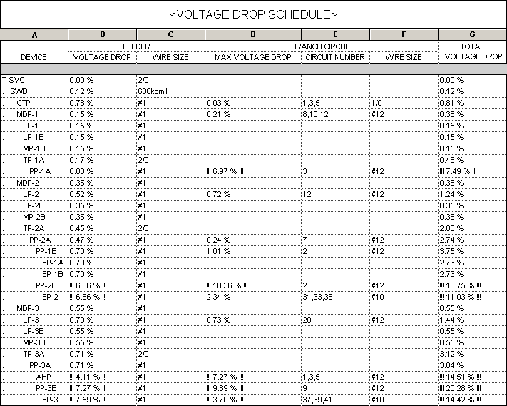
The default schedule layout is shown below. Information about the voltage drop at the upstream feeder for each piece of distribution equipment in the project is listed. The devices are ordered based upon the connections between devices in the model.
Once the schedule is created, you can modify it using standard Revit tools.
By default, the VOLTAGE DROP columns use shared parameters that display a warning if the value exceeds thresholds set in the Voltage Drop Project Options. To display voltage drop without warnings for one or more of these columns, use the alternative shared parameters available for voltage drop.
There are several options that affect how voltage drop is calculated. Visit the Voltage Drop Project Options section for more information.
Output shared parameter values as uppercase: Sets whether shared parameter outputs are displayed only in uppercase letters.
Feeder wire make-up length: Sets additional length to be added to feeders for connections, which can impact voltage drop calculations.
Branch circuit wire make-up length: Sets additional length to be added to branch circuits for connections, which can impact voltage drop calculations.