Neutrals
Neutrals cannot be added to or removed from feeders and branch circuits using ElectroBIM commands. Whether the software includes a neutral is based upon the Revit settings described below.
Distribution Equipment
Revit includes a neutral on feeders to distribution equipment based upon the settings of the Distribution System chosen for the equipment.
You can modify the Distribution System settings using the Manage→MEP Settings→Electrical Settings command. From the tree on the left side of the dialog box, select Distribution Systems.
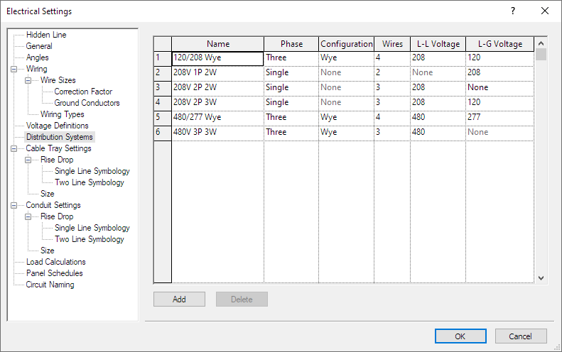
Using the table below as a reference, configure the neutrals for your distribution systems.
| Single-Phase Single Pole | Single-Phase Two Pole | Three-Phase | |
|---|---|---|---|
| Neutral | Phase ▾ to Single Wires ▾ to 2 | Phase ▾ to Single Wires ▾ to 3 L-G Voltage ▾ to not None | Phase ▾ to Three Wires ▾ to 4 |
| No Neutral | N/A | Phase ▾ to Single Wires ▾ to 3 L-G Voltage ▾ to None | Phase ▾ to Three Wires ▾ to 3 |
Branch Circuits (2025 & Older)
Revit 2025 and older versions include a neutral on branch circuits if the load is unbalanced or if the wiring type requires a neutral.
Edit the family of the device on the circuit, select the connector, and set the System Type to Power - Balanced or Power - Unbalanced as appropriate for the loads on the device. If set to Power - Unbalanced, Revit will include a neutral on the circuit.
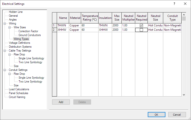
To set the neutral requirement, use the Manage→MEP Settings→Electrical Settings command. From the tree on the left side of the dialog box, select Wiring→Wiring Types. For each wire type listed, check or uncheck the ☐ Neutral Required box as appropriate.
To set the Wire Type used to determine whether the branch circuit has a neutral, select a device connected to the circuit. Select the Electrical Circuits tab on the ribbon. In the Properties panel, you can change the Wire Type value.
Branch Circuits (2026 & Newer)
Revit 2026 and newer versions include a neutral on branch circuits based upon the settings of the Cable Size chosen for the circuit.
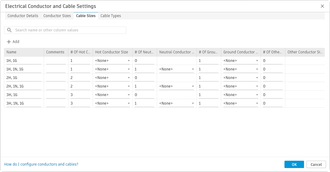
To define your cable sizes, use the Manage→MEP Settings→Electrical Conductor and Cable Settings command. On the Cable Sizes tab, define at least one cable size that has # of Neutrals ▾ set to 0, and at least one cable size that has # of Neutrals ▾ set to 1. None of the other settings need to be configured for ElectroBIM to set the wire sizes, number of conductors, or whether the circuit has a ground. Make sure the cable sizes defined are assigned to at least one Cable Type in the Cable Types tab.
If you use Revit tick marks, you will need to define additional cable sizes for each configuration of wires as shown in the image below: 1 hot with or without a neutral or ground, 2 hots with or without a neutral or ground, and so on. You do not need to set sizes for any of the wires.
To set the Cable Size used to determine whether the branch circuit has a neutral, select a device connected to the circuit. Select the Electrical Circuits tab on the ribbon. In the Properties panel, you can change the Cable Type and Cable Size values.