Performing Selective Coordination
How to perform selective coordination.
Start in the SELECTIVE COORDINATION drafting view.
Set Breaker Curves for Transformer T1 & Panel DP
-
Run the
ElectroBIM Design→ command. If prompted to select a distribution equipment to edit, press ESC. The Panel Edit dialog box will open. Panel Edit
 -
Select transformer T1 from the list.
-
Beside OCP Trip ▾, press the button. The OCP Device Settings dialog box will open.
-
Press the button. The OCP Curve Search dialog box will open.
-
In the Filter field, enter Eaton PDG Thermal.
-
Select the Eaton->Molded Case Circuit Breaker->Power Defense->Frame 1->PDG->Thermal Magnetic breaker highlighted in green.
-
Press the button to close the OCP Curve Search dialog box, then press the to close the OCP Device Settings dialog box.
-
Select panel DP from the list and, beside Main Disconnect Trip ▾, press the button. The OCP Device Settings dialog box will open.
-
Press the button. The OCP Curve Search dialog box will open.
-
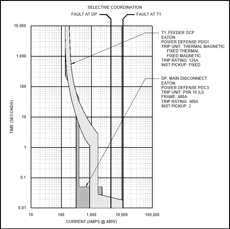
Search for and select the Eaton->Molded Case Circuit Breaker->Power Defense->Frame 3->PDC3->PXR 10 | Power Defense PDC3, Trip Unit: PXR 10 (LI), Frame: 250A breaker highlighted in green.
-
Press the button to close the OCP Curve Search dialog box, then press the to close the OCP Device Settings dialog box.
-
Press the button to close the dialog box.
Create the Selective Coordination Graph
-
Run the
ElectroBIM Design→ command. The Insert Selective Coordination Graph dialog box will open. Graph Insert
 -
Press the button. The Select Distribution Equipment dialog box will open.
-
Select transformer T1 from the list and press the button to close the dialog box.
-
Repeat steps 2-3 for panel DP. When asked which OCP device you want to display on the graph, select .
-
Press the button to close the dialog box.
-
Follow the prompts to insert the graph on the drafting view.
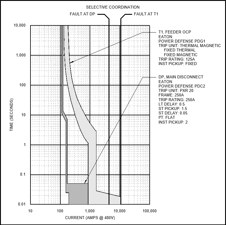
Modify the Breaker Curve
-
Run the
ElectroBIM Design→ command. Panel Edit -
On the graph, select the curve or label for panel DP. The Panel Edit dialog box will open.
-
Set Main Disconnect Trip ▾ to 250.
-
Beside Main Disconnect Trip ▾, press the button. The OCP Device Settings dialog box will open.
-
Using the button or the Group ☰ list, set the breaker to Eaton->Molded Case Circuit Breaker->Power Defense->Frame 2->PDC2->PXR 20 | Power Defence PDC2, Trip Unit: PXR 20, Frame: 250A.
-
Press the button to close the dialog box.
-
Press the button to close the dialog box.
The graph will update to reflect the changes.