Project Options

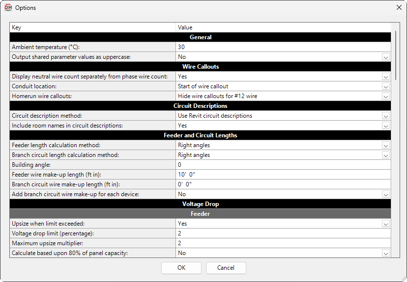
Allows you to control the output of ElectroBIM to match your preferred standards. Opens the Options dialog box:
Options Dialog Box
Editing a Setting
To edit an option setting, select the Value ☰ in the list and enter a new value.
Press the button to save your changes.
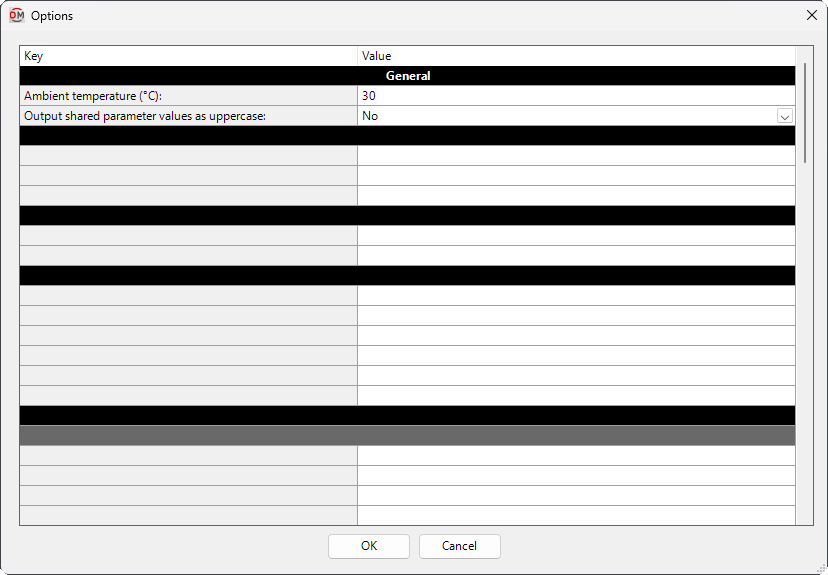
General
-
Ambient temperature: The ambient temperature in °C used to determine the ampacities of conductors based upon NEC 310.15(B). The recommended value for most projects is 30.
-
Output shared parameter values as uppercase: ▾ The format used for the case of default shared parameter values. User-specified values always use the text exactly as input by the user.
- Yes Shared parameters use all uppercase letters for fixed values.
- No Shared parameters use a mix of uppercase and lowercase letters for fixed values.
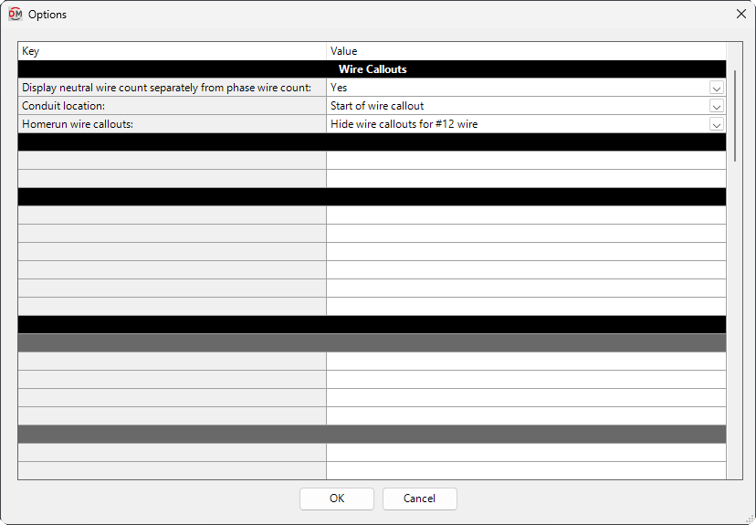
Wire Callouts
-
Display neutral wire count separately from phase wire count: ▾ Whether neutral and hot wires are listed together or separately when they are the same size.
- Yes The neutral wire count is listed separately from the phase wire count.
Example: 1/2"C,3#12,#12N,#12G - No The neutral wire count and the phase wire count are added together.
Example: 1/2"C,4#12,#12G
- Yes The neutral wire count is listed separately from the phase wire count.
-
Conduit location: ▾ Where the conduit size is displayed in the wire callout.
- Start of wire callout The conduit size is located at the start of the wire callout.
Example: 1/2"C,3#12,#12N,#12G - End of wire callout The conduit size is located at the end of the wire callout.
Example: 3#12,#12N,#12G,1/2"C
- Start of wire callout The conduit size is located at the start of the wire callout.
-
Homerun wire callouts: ▾ Whether homerun tags that use the DMET_Circuit_WireCalloutHR shared parameter display a wire callout.
- Display wire callout for all homeruns The wire callout is always displayed.
- Hide wire callouts for #12 wire The wire callout is not displayed for #12 homeruns. Wire callouts are displayed for larger homeruns.
- Hide wire callouts for #12 wire on 1-pole circuits The wire callout is not displayed for #12 homeruns on single-pole circuits. Wire callouts are displayed for larger homeruns or #12 homeruns on multi-pole circuits.
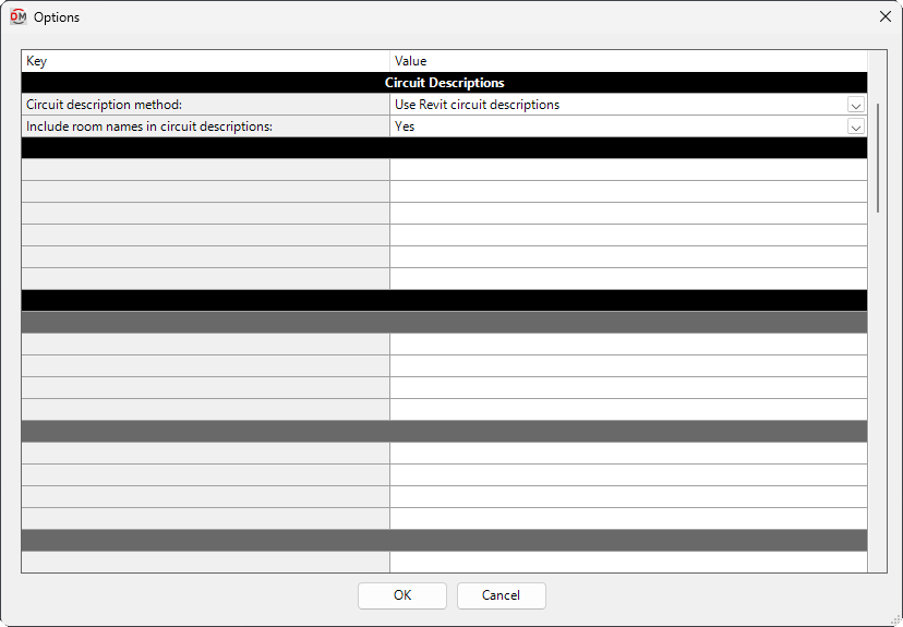
Circuit Descriptions
-
Circuit description method: ▾ Whether circuit descriptions are controlled through ElectroBIM commands.
- Use Revit circuit descriptions Circuit descriptions are set in the panel schedule or Load Name parameter using standard Revit functionality. Circuit descriptions set using the Family Edit command are ignored. Circuit description settings in other
Edit commands are removed, or locked with Controlled by Revit displayed. - Use ElectroBIM circuit descriptions Circuit descriptions are set using the
Edit commands. See the Circuit Descriptions in ElectroBIM article in the knowledge base for more information.
- Use Revit circuit descriptions Circuit descriptions are set in the panel schedule or Load Name parameter using standard Revit functionality. Circuit descriptions set using the Family Edit command are ignored. Circuit description settings in other
-
Include room names in circuit descriptions: ▾ Whether circuit descriptions include room names. If Circuit description method ▾ is set to Use Revit circuit descriptions, this option is ignored.
- Yes Circuit descriptions include a list of all of the rooms served by the circuits. The names of each area containing devices on the circuit will be listed. Each area is listed once in the circuit description.
- No Circuit descriptions do not include room names.
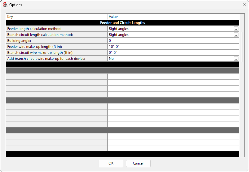
Feeder and Circuit Lengths
-
Feeder length calculation method: ▾ How the feeder lengths are calculated between distribution equipment.
- Straight line The lengths are calculated based upon the straight line distance between the distribution equipment and item connected to it. This calculation approximates lengths for wires running directly between devices, typically underground.
- Right angles The lengths are calculated based upon the distance along the axes of the building between the distribution equipment and item connected to it. This calculation approximates lengths for wires running along the walls of the building.
- Revit calculated length The lengths are based upon the distance that Revit calculates using the Circuit Path feature.
-
Branch circuit length calculation method: ▾ How the branch circuit lengths are calculated between distribution equipment and connected devices.
- Straight line The lengths are calculated based upon the straight line distance between the distribution equipment and item connected to it. This calculation approximates lengths for wires running directly between devices, typically underground.
- Right angles The lengths are calculated based upon the distance along the axes of the building between the distribution equipment and item connected to it. This calculation approximates lengths for wires running along the walls of the building.
- Revit calculated length The lengths are based upon the distance that Revit calculates using the Circuit Path feature.
-
Building angle: The orientation of the building used when the Feeder length calculation method ▾ or Branch circuit length calculation method ▾ is set to Right angles. See the How Building Angle Affects Calculations article in the knowledge base for more information about this setting.
-
Feeder wire make-up length: Additional length of wire added to automatically calculated feeder lengths to represent make-up in the field.
-
Branch circuit wire make-up length: Additional length of wire added to automatically calculated branch circuit lengths to represent make-up in the field.
-
Add branch circuit wire make-up for each device: ▾ Whether the length specified in Branch circuit wire make-up length is added for each device on the circuit.
- Yes The length is added for each device on the circuit.
- No The length is added once, regardless of the number of devices on the circuit.
Voltage Drop
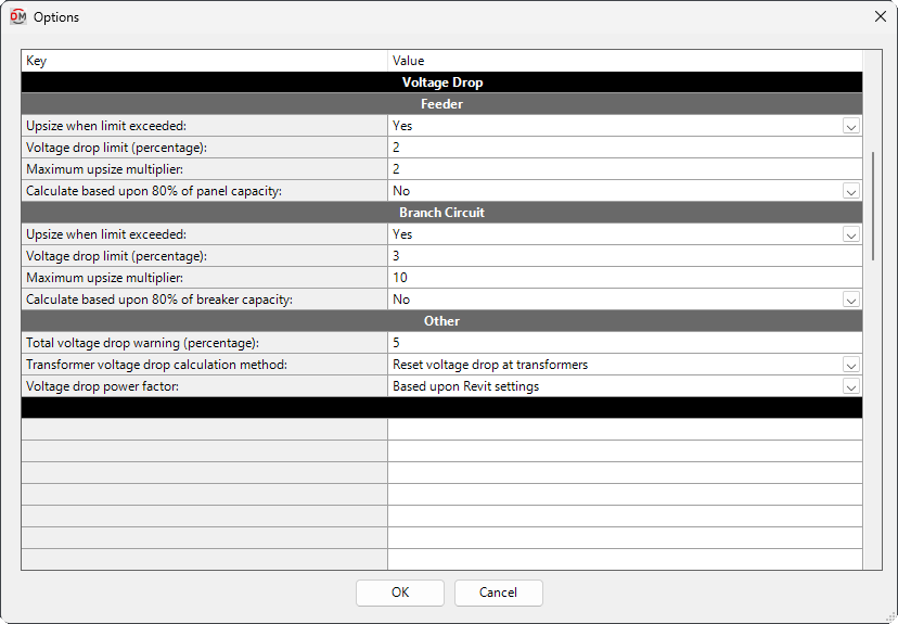
Feeder
-
Upsize when limit exceeded: ▾ Whether automatically sized feeders will be upsized to reduce voltage drop that exceeds the Feeder Voltage drop limit.
-
Voltage drop limit: The maximum voltage drop percentage allowed on feeders. Voltage drop percentages above this value will be highlighted in the parameter output.
-
Maximum upsize multiplier: The maximum amount by which the wire ampacity of feeders will be upsized to reduce voltage drop.
Example: If set to 2, a 100A feeder will be upsized to no larger than 200A. -
Calculate based upon 80% of panel capacity: ▾ The load used when calculating voltage drop on distribution equipment.
- Yes The calculation is made based upon 80% of panel capacity.
- No The calculation is made based upon the calculated load on the distribution equipment.
Branch Circuit
-
Upsize when limit exceeded: ▾ Whether automatically sized branch circuits will be upsized to reduce voltage drop that exceeds the Branch Circuit Voltage drop limit.
-
Voltage drop limit: The maximum voltage drop percentage allowed on branch circuits. Voltage drop percentages above this value will be highlighted in the parameter output.
-
Maximum upsize multiplier: The maximum amount by which the wire ampacity of branch circuits will be upsized to reduce voltage drop.
Example: If set to 2, a 15A branch circuit will be upsized to no larger than 30A. -
Calculate based upon 80% of breaker capacity: ▾ The load used when calculating voltage drop on branch circuits.
- Yes The calculation is made based upon 80% of breaker capacity.
- No The calculation is made based upon the calculated load on the branch circuit.
Other
-
Total voltage drop warning: The warning threshold for the total maximum voltage drop percentage on branch circuits including voltage drop from upstream feeders. Voltage drop percentages above this value will be highlighted in the parameter output.
-
Transformer voltage drop calculation method: ▾ How voltage drop is calculated through transformers. See the Voltage Drop and Transformers Options article in the knowledge base for more information.
- Include transformers in voltage drop The voltage drop through the transformer is calculated and added to the voltage drop on the feeder. The voltage drop through the upstream feeders is carried through the transformer.
- Ignore transformers The voltage drop through the transformer is ignored when the voltage drop for the system is calculated. The voltage drop through the upstream feeders is carried through the transformer.
- Reset voltage drop at transformers The voltage drop is reset to 0% at each transformer. The voltage drop through the transformer is ignored. The voltage drop through the upstream feeders is ignored.
-
Voltage drop power factor: ▾ The power factor used when calculating voltage drop.
- Based upon Revit settings The power factor for each device is based upon the connector settings in the device family.
- Fixed at 0.85 The calculation is made based upon a power factor of 0.85.
Selective Coordination Graph
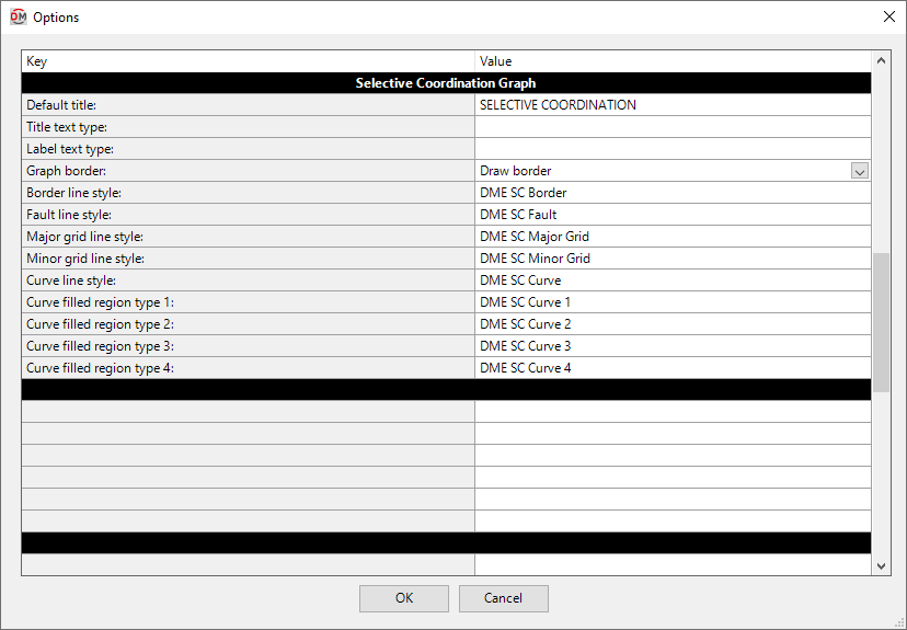
These options are used to customize selective coordination graphs created using the Graph Insert command. See the Customizing Selective Coordination Graphs in ElectroBIM article in the knowledge base for more information.
-
Default title: The default text that is entered in the Title field when running the Graph Insert command.
-
Title text type: The default text type for the title of the graph.
warningIf this field is blank, the title will use the most recent text type used in the project.
-
Label text type: The default text type for all of the text on the graph except for the title.
warningIf this field is blank, the labels will use the most recent text type used in the project.
-
Graph border: ▾ Whether a border is drawn around the outside of the graph.
- Draw border Graphs will be drawn with a border.
- No border Graphs will be drawn without a border.
-
Border line style: The line style used to draw the border around the graph.
-
Fault line style: The line style used to draw the device fault on the graph.
-
Major grid line style: The line style used to draw the major grid lines on the graph, such as those at 1 second and 10 seconds.
-
Minor grid line style: The line style used to draw the minor grid lines on the graph, such as those between 1 second and 10 seconds.
-
Curve line style: The line style used to draw the curves on the graph.
-
Curve filled region type 1:, Curve filled region type 2:, Curve filled region type 3:, Curve filled region type 4: The filled region used for the first, second, third, and fourth curve on the graph, respectively.
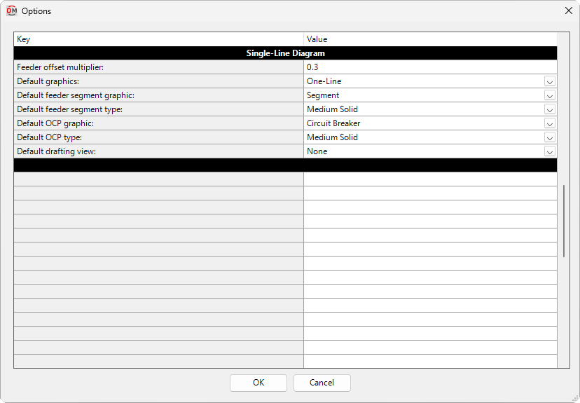
Single-Line Diagram
-
Feeder offset multiplier: The distance between feeders inserted using the Insert Create, Copy Create, Power, Insert Link, Generate One-Line, and Generate Riser commands.
-
Default graphics: ▾ Whether devices with single-line diagram graphics set to Use project options setting use the graphics set in the Generate One-Line or Generate Riser section.
-
Default feeder segment graphic: ▾ The graphic family used by feeder segments that do not have additional graphics. The values in this list are based upon the Single-Line Diagram Feeder Graphics command.
-
Default feeder segment type: ▾ The graphic type used for the selected Default feeder segment graphic ▾.
-
Default OCP graphic: ▾ The graphic family used for the OCP on feeders inserted using the Insert Create, Copy Create, Power, Insert Link, Generate One-Line, and Generate Riser commands. The values in this list are based upon the Single-Line Diagram Feeder Graphics command.
-
Default OCP type: ▾ The graphic type used for the selected Default panel OCP graphic ▾.
-
Default drafting view: ▾ The drafting view onto which device graphics will be inserted when using the Insert Link command in a model view.
- None You will be prompted to select a drafting view each time you insert a device.
- Specific drafting view The device graphic will be added to the drafting view chosen from the list. The values in this list are based upon the drafting views in the project.
Generate One-Line
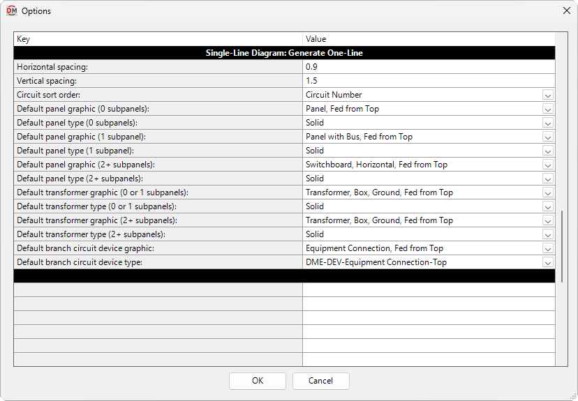
These options set the graphics and other settings used when single-line diagram graphics are inserted using the Generate One-Line command.
-
Horizontal spacing: The minimum horizontal distance between equipment inserted on the drafting view, as a multiple of the drawing scale.
-
Vertical spacing: The minimum vertical distance between equipment inserted on the drafting view, as a multiple of the drawing scale.
-
Circuit sort order: ▾ The order in which equipment will be inserted on the drafting view from left to right.
- Breaker Size Equipment will be inserted by OCP size from largest to smallest. Equipment with the same OCP size will be inserted by name in alphabetical order.
- Circuit Number Equipment will be inserted by circuit number beginning with circuit 1. Equipment downstream from panels will be inserted beginning with odd circuits, then even circuits.
- Equipment Name Equipment will be inserted by name in alphabetical order.
-
Default panel graphic (0 subpanels): ▾ The graphic family used by panels with no downstream distribution equipment. The values in this list are based upon the Single-Line Diagram Device Graphics command.
-
Default panel type (0 subpanels): ▾ The graphic type used for the selected Default panel graphic (0 subpanels) ▾.
-
Default panel graphic (1 subpanel): ▾ The graphic family used by panels with 1 downstream distribution equipment. The values in this list are based upon the Single-Line Diagram Device Graphics command.
-
Default panel type (1 subpanel): ▾ The graphic type used for the selected Default panel graphic (1 subpanel) ▾.
-
Default panel graphic (2+ subpanels): ▾ The graphic family used by panels with 2 or more downstream distribution equipment. The values in this list are based upon the Single-Line Diagram Device Graphics command.
-
Default panel type (2+ subpanels): ▾ The graphic type used for the selected Default panel graphic (2+ subpanels) ▾.
-
Default transformer graphic (0 or 1 subpanels): ▾ The graphic family used by transformers with 0 or 1 downstream distribution equipment. The values in this list are based upon the Single-Line Diagram Device Graphics command.
-
Default transformer type (0 or 1 subpanels): ▾ The graphic type used for the selected Default transformer graphic (0 or 1 subpanels) ▾.
-
Default transformer graphic (2+ subpanels): ▾ The graphic family used by transformers with 2 or more downstream distribution equipment. The values in this list are based upon the Single-Line Diagram Device Graphics command.
-
Default transformer type (2+ subpanels): ▾ The graphic type used for the selected Default transformer graphic (2+ subpanels) ▾.
-
Default branch circuit device graphic: ▾ The graphic family used by branch circuit devices. The values in this list are based upon the Single-Line Diagram Device Graphics command.
-
Default branch circuit device type: ▾ The graphic type used for the selected Default branch circuit device graphic ▾.
Generate Riser
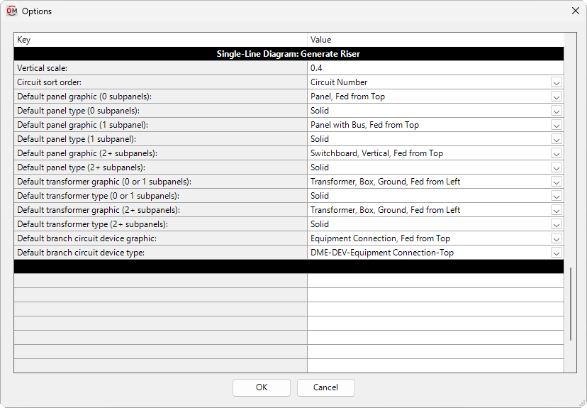
These options set the graphics and other settings used when single-line diagram graphics are inserted using the Generate Riser command.
-
Vertical scale: The vertical distance used to display elevation differences between equipment on the drafting view, as a multiple of the drawing scale and elevation difference.
-
Circuit sort order: ▾ The order in which equipment will be inserted on the drafting view from left to right.
- Breaker Size Equipment will be inserted by OCP size from largest to smallest. Equipment with the same OCP size will be inserted by name in alphabetical order.
- Circuit Number Equipment will be inserted by circuit number beginning with circuit 1. Equipment downstream from panels will be inserted beginning with odd circuits, then even circuits.
- Equipment Name Equipment will be inserted by name in alphabetical order.
-
Default panel graphic (0 subpanels): ▾ The graphic family used by panels with no downstream distribution equipment. The values in this list are based upon the Single-Line Diagram Device Graphics command.
-
Default panel type (0 subpanels): ▾ The graphic type used for the selected Default panel graphic (0 subpanels) ▾.
-
Default panel graphic (1 subpanel): ▾ The graphic family used by panels with 1 downstream distribution equipment. The values in this list are based upon the Single-Line Diagram Device Graphics command.
-
Default panel type (1 subpanel): ▾ The graphic type used for the selected Default panel graphic (1 subpanel) ▾.
-
Default panel graphic (2+ subpanels): ▾ The graphic family used by panels with 2 or more downstream distribution equipment. The values in this list are based upon the Single-Line Diagram Device Graphics command.
-
Default panel type (2+ subpanels): ▾ The graphic type used for the selected Default panel graphic (2+ subpanels) ▾.
-
Default transformer graphic (0 or 1 subpanels): ▾ The graphic family used by transformers with 0 or 1 downstream distribution equipment. The values in this list are based upon the Single-Line Diagram Device Graphics command.
-
Default transformer type (0 or 1 subpanels): ▾ The graphic type used for the selected Default transformer graphic (0 or 1 subpanels) ▾.
-
Default transformer graphic (2+ subpanels): ▾ The graphic family used by transformers with 2 or more downstream distribution equipment. The values in this list are based upon the Single-Line Diagram Device Graphics command.
-
Default transformer type (2+ subpanels): ▾ The graphic type used for the selected Default transformer graphic (2+ subpanels) ▾.
-
Default branch circuit device graphic: ▾ The graphic family used by branch circuit devices. The values in this list are based upon the Single-Line Diagram Device Graphics command.
-
Default branch circuit device type: ▾ The graphic type used for the selected Default branch circuit device graphic ▾.
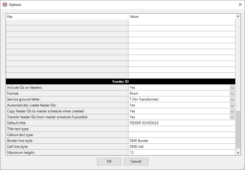
Feeder ID
-
Include IDs on feeders: ▾ Whether feeder IDs appear on the single-line diagram.
-
Format: ▾ Sets how feeder IDs are generated. See the Feeder IDs article in the knowledge base for more information.
-
Service ground letter: ▾ Sets the letter used when feeder IDs are generated to indicate a service ground. The available options are T, J, and S.
-
Automatically create feeder IDs: ▾ Whether feeder IDs are automatically generated.
- Yes Feeder IDs are generated automatically based upon the feeder ID Format ▾.
- No When a feeder ID is generated, the New Feeder Callout ID dialog box will appear. You can then set the feeder ID, feeder ID group, and whether feeder IDs should be automatically generated in the future.
-
Export feeder IDs to master schedule when possible: ▾ Whether feeder IDs are copied to the Master Feeder ID Schedule when they are generated.
-
Import feeder IDs from master schedule when possible: ▾ When a feeder ID is generated with the same specifications as an existing feeder ID in the master schedule, this option sets whether a new feeder ID is generated or the existing feeder ID is used.
-
Default title: The default text that is entered in the feeder schedule title when running the Schedule Insert command.
-
Title text type: The default text type for the feeder schedule title.
warningIf this field is blank, the feeder schedule title will use the most recent text type used in the project.
-
Callout text type: The default text type for the feeder callouts in the feeder schedule.
warningIf this field is blank, the feeder callouts will use the most recent text type used in the project.
-
Border line style: The line style used to draw the border around the feeder schedule and title.
-
Cell line style: The line style used to draw the lines between cells in the feeder schedule.
-
Maximum height: The maximum height of the feeder schedule. This value corresponds to inches on the printed page. When the schedule exceeds this height, it will be continued in subsequent schedules next to the first.