Single-Line Diagram Feeder Graphics

Allows you to customize the list of graphic families available to be used on feeders on the single-line diagram.
Opens the Single-Line Diagram Feeder Graphics dialog box:
Single-Line Diagram Feeder Graphics Dialog Box
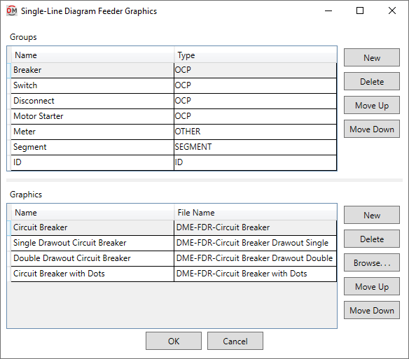
Groups
This section is used to determine how graphic families are grouped and displayed in commands and fields that allow you to set single-line diagram graphics for feeders.
-
Name The name that is displayed in the Group ▾ field in the Add/Modify Graphic and Circuit Insert commands.
-
Type ▾ The feeder graphic type with which the group will be associated when populating feeder graphics fields and lists.
-
OCP The group will be displayed when specifying an OCP graphic.
-
SEGMENT The group will be displayed when adding or modifying a non-OCP graphic in the Add/Modify Graphic command.
Graphic families in this group will be available in the Default feeder segment graphic ▾ option in the Project Options command.
-
ID The group will be displayed when specifying a feeder ID graphic.
-
OTHER The group will be displayed when adding or modifying a non-OCP graphic in the Add/Modify Graphic command.
-
-
Creates a new group.
-
Deletes the current group.
-
Moves the selected group up in the list.
-
Moves the selected group down in the list.
Graphics
This section is used to determine which graphic families are available to be selected in the active group.
-
Name The name of the graphic family that is displayed in fields and lists.
-
File Name The file name of the graphic family displayed on the single-line diagram, not including the file extension.
-
Creates a new row. The new row will use the same settings as the selected row when the button was pressed.
-
Deletes the current row.
-
Press this button to select a file for the current graphic.
-
Moves the selected graphic up in the list.
-
Moves the selected graphic down in the list.