Family Edit

Allows you to view and edit additional electrical information added to a family.
Opens the Family Edit dialog box. The information displayed in the dialog box is based upon the Device Type ▾. The dialog box for each device type is described below.
-
Device Type: ▾ Controls how the family is handled by ElectroBIM. Each selection provides a different set of values that can be specified.
- Branch circuit device: Other A generic branch circuit device. Includes the option to set the circuit description and whether the device needs an isolated ground.
- Branch circuit device: Equipment connection An equipment connection. Includes options for setting breaker and wire sizing and motor-specific values for fault calculations.
- Distribution equipment: Other A generic distribution equipment. Includes options for ground and neutral wire sizing, whether the equipment needs an isolated ground, and setting descriptions in the upstream distribution equipment.
- Distribution equipment: Panel A panel. Includes options for setting the bus size and main disconnect information.
- Distribution equipment: Transformer A transformer. Includes options for setting transformer-specific information.
-
List ☰ All of the family types in the family, listed alphabetically.
You can select multiple types in the list using the SHIFT or CTRL key.
-
Press this button to copy the settings from a family type to the family type(s) selected in the list.
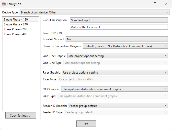
Branch Circuit Device: Other
These values are displayed when the Device Type ▾ is set to Branch circuit device: Other.
-
Circuit Description: The description that will be displayed on circuits to which this device is connected.
- Standard input Enter a circuit description in the field provided.
- Based on parameter The value for the specified parameter will be used. Press the button to select a parameter. See the Using Non-ElectroBIM Parameters for ElectroBIM Settings article in the knowledge base for more information.
-
Load: The load defined on the connectors in the family. This value is read-only and cannot be changed in this dialog box. Modify the values in the connectors to change this value.
-
Isolated Ground: ▾ Whether the branch circuit needs an isolated ground wire. If set to Yes, an isolated ground wire is included in the wire callout for the branch circuit connected to this device.
-
Show on Single-Line Diagram: ▾ Whether the device is inserted on the single-line diagram when using the Generate One-Line or Generate Riser commands, and whether it is displayed in the Insert Link and Copy Link commands. The default setting for branch circuit devices is No.
-
One-Line Graphic: ▾ The default graphic family used for the device when it is inserted on a one-line diagram. The values in this list are based upon the Single-Line Diagram Device Graphics command.
- Use project options setting The Default branch circuit device graphic ▾ specified in the Generate One-Line Project Options for the project will be used.
-
One-Line Type: ▾ The graphic type used for the device. The values in this list are based upon the selected One-Line Graphic ▾.
-
Riser Graphic: ▾ The default graphic family used for the device when it is inserted on a riser diagram. The values in this list are based upon the Single-Line Diagram Device Graphics command.
- Use project options setting The Default branch circuit device graphic ▾ specified in the Generate Riser Project Options for the project will be used.
-
Riser Type: ▾ The graphic type used for the device. The values in this list are based upon the selected Riser Graphic ▾.
-
OCP Graphic: ▾ The graphic family used for the upstream OCP when the device is inserted on the single-line diagram. The values in this list are based upon the Single-Line Diagram Feeder Graphics command.
- Use upstream distribution equipment graphic The Default Downstream OCP Graphic ▾ and Default Downstream OCP Type ▾ specified in the upstream distribution equipment will be used.
- None No OCP graphic will be inserted.
-
OCP Type: ▾ The graphic type used for the upstream OCP. The values in this list are based upon the selected OCP Graphic ▾.
-
Feeder ID Graphic: ▾ The graphic family used for the feeder ID when the device is inserted on the single-line diagram. The values in this list are based upon the Single-Line Diagram Feeder Graphics command.
- Feeder group default The feeder ID graphic specified for the group in the Project Feeder ID Schedule will be used.
- None No feeder ID graphic will be inserted.
-
Feeder ID Type: ▾ The graphic type used for the feeder ID. The values in this list are based upon the selected Feeder ID Graphic ▾.
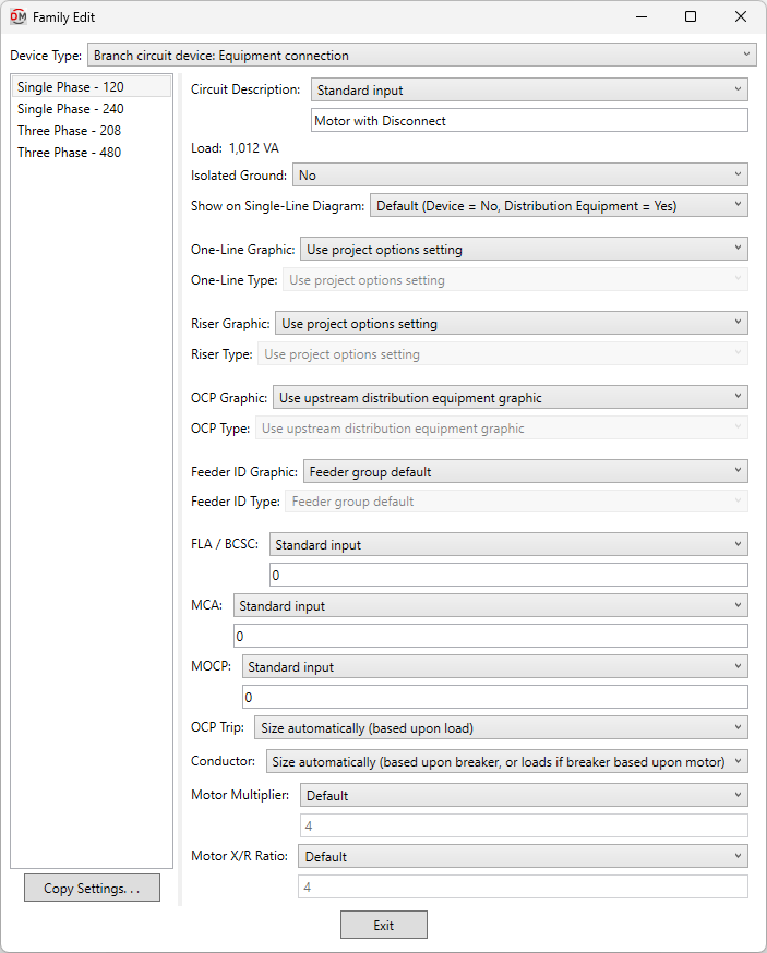
Branch Circuit Device: Equipment Connection
These values are displayed when the Device Type ▾ is set to Branch circuit device: Equipment connection.
-
Circuit Description: The description that will be displayed on circuits to which this device is connected.
- Standard input Enter a circuit description in the field provided.
- Based on parameter The value for the specified parameter will be used. Press the button to select a parameter. See the Using Non-ElectroBIM Parameters for ElectroBIM Settings article in the knowledge base for more information..
-
Load: The load defined on the connectors in the family. This value is read-only and cannot be changed in this dialog box. Modify the values in the connectors to change this value.
-
Isolated Ground: ▾ Whether the branch circuit needs an isolated ground wire. If set to Yes, an isolated ground wire is included in the wire callout for the branch circuit connected to this device.
-
Show on Single-Line Diagram: ▾ Whether the device is inserted on the single-line diagram when using the Generate One-Line or Generate Riser commands, and whether it is displayed in the Insert Link and Copy Link commands. The default setting for branch circuit devices is No.
-
One-Line Graphic: ▾ The default graphic family used for the device when it is inserted on a one-line diagram. The values in this list are based upon the Single-Line Diagram Device Graphics command.
- Use project options setting The Default branch circuit device graphic ▾ specified in the Generate One-Line Project Options for the project will be used.
-
One-Line Type: ▾ The graphic type used for the device. The values in this list are based upon the selected One-Line Graphic ▾.
-
Riser Graphic: ▾ The default graphic family used for the device when it is inserted on a riser diagram. The values in this list are based upon the Single-Line Diagram Device Graphics command.
- Use project options setting The Default branch circuit device graphic ▾ specified in the Generate Riser Project Options for the project will be used.
-
Riser Type: ▾ The graphic type used for the device. The values in this list are based upon the selected Riser Graphic ▾.
-
OCP Graphic: ▾ The graphic family used for the upstream OCP when the device is inserted on the single-line diagram. The values in this list are based upon the Single-Line Diagram Feeder Graphics command.
- Use upstream distribution equipment graphic The Default Downstream OCP Graphic ▾ and Default Downstream OCP Type ▾ set in the upstream distribution equipment will be used.
- None No OCP graphic will be inserted.
-
OCP Type: ▾ The graphic type used for the upstream OCP. The values in this list are based upon the selected OCP Graphic ▾.
-
Feeder ID Graphic: ▾ The graphic family used for the feeder ID when the device is inserted on the single-line diagram. The values in this list are based upon the Single-Line Diagram Feeder Graphics command.
- Feeder group default The feeder ID graphic set for the group in the Project Feeder ID Schedule will be used.
- None No feeder ID graphic will be inserted.
-
Feeder ID Type: ▾ The graphic type used for the feeder ID. The values in this list are based upon the selected Feeder ID Graphic ▾.
-
FLA / BCSC: The full load amps (FLA) or branch circuit selection current (BCSC).
BCSC is used to size the breaker and wires for motor-compressors per NEC 440.22 (A) & (C) and NEC 440.32 & 33.
FLA is used to size breakers for motors per NEC 430.52.
- Based on parameter The value for the specified parameter will be used. Press the button to select a parameter. See the Using Non-ElectroBIM Parameters for ElectroBIM Settings article in the knowledge base for more information..
-
MCA: The minimum circuit amps (MCA). Used to size wires for multimotors per NEC 440.35.
- Based on parameter The value for the specified parameter will be used. Press the button to select a parameter. See the Using Non-ElectroBIM Parameters for ElectroBIM Settings article in the knowledge base for more information..
-
MOCP: The maximum overcurrent protection (MOCP). Used to size the breaker for motor-compressors per NEC 440.22(A) & (C).
- Based on parameter The value for the specified parameter will be used. Press the button to select a parameter. See the Using Non-ElectroBIM Parameters for ElectroBIM Settings article in the knowledge base for more information..
-
OCP Trip: ▾ How to size the breaker for the branch circuit to which the instance is connected.
- Size automatically (based upon load) The breaker is sized based upon 125% of the connected load. FLA / BCSC, MCA, and MOCP are all ignored.
- Motor-compressor, <= MOCP The breaker is sized to be less than the MOCP per NEC 440.22(C).
- Motor-compressor, <= 175% of BCSC, <= MOCP The breaker is sized to be less than 175% of the BCSC and less than the MOCP per NEC 440.22(A) & (C).
- Motor-compressor, <= 225% of BCSC, <= MOCP The breaker is sized to be less than 225% of the BCSC and less than the MOCP per NEC 440.22(A) Exception no. 2 & (C).
- Motor, dual element fuse, <= 175% of FLA The breaker is sized to be less than 175% of the FLA per NEC 430.52.
- Motor, dual element fuse, <= 225% of FLA The breaker is sized to be less than 225% of the FLA per NEC 430.52(C)(1)(b)(2).
- Motor, inverse time breaker, <= 250% of FLA The breaker is sized to be less than 250% of the FLA per NEC 430.52.
- Based on parameter The value for the specified parameter will be used. Press the button to select a parameter. See the Using Non-ElectroBIM Parameters for ElectroBIM Settings article in the knowledge base for more information..
- Custom The breaker size is set to the value you specify. Enter a value that corresponds to an ampacity in the Wire Ampacities command in your project.
-
Conductor: ▾ How to size the conductors for the branch circuit to which the instance is connected.
- Size automatically (based upon breaker, or loads if breaker based upon motor) The conductors are sized automatically. The conductors are sized to match the breaker, or match the load if OCP Trip ▾ is set to one of the Motor choices.
- Multimotor, >= MCA The conductors are sized to be greater than the MCA per NEC 440.35.
- Motor-compressor, >= 100% of BCSC + 25% of max BCSC The conductors are sized to be greater than 100% of the combined BCSC, plus 25% of the largest BCSC on the circuit per NEC 440.32 & 33.
- Size based upon loads The conductors are sized based upon 125% of the connected load.
- Size based upon breaker The conductors are sized based upon the breaker size.
- Based on parameter The value for the specified parameter will be used. Press the button to select a parameter. See the Using Non-ElectroBIM Parameters for ElectroBIM Settings article in the knowledge base for more information..
- Custom The conductors are sized based upon the ampacity value you specify. Enter a value that corresponds to an ampacity in the Wire Ampacities command in your project.
-
Motor Multiplier: ▾ The multiplier applied to the motor load when it is used during fault calculations.
- Default A value of 4 will be used.
- Custom Enter a value in the field provided.
-
Motor X/R Ratio: ▾ The X/R ratio of the motor load when it is used during fault calculations.
- Default A value of 5 will be used.
- Custom Enter a value in the field provided.
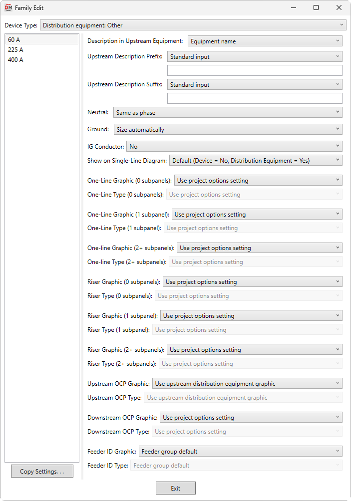
Distribution Equipment: Other
These values are displayed when the Device Type ▾ is set to Distribution equipment: Other.
-
Description in Upstream Equipment: ▾ The description for the distribution equipment that will appear in the circuit description of the upstream panel schedule, along with the Upstream Description Prefix and Upstream Description Suffix specified.
- Equipment name The description in the upstream panel schedule will be the same as the device name.
- Custom Enter a custom description in the field provided.
- Based on parameter The value for the specified parameter will be used. Press the button to select a parameter. See the Using Non-ElectroBIM Parameters for ElectroBIM Settings article in the knowledge base for more information..
-
Upstream Description Prefix: A prefix added to the start of the circuit description in the upstream equipment. The default description is the name of the family instance.
- Based on parameter The value for the specified parameter will be used. Press the button to select a parameter. See the Using Non-ElectroBIM Parameters for ElectroBIM Settings article in the knowledge base for more information..
-
Upstream Description Suffix: A suffix added to the end of the circuit description in the upstream equipment. The default description is the name of the family instance.
- Based on parameter The value for the specified parameter will be used. Press the button to select a parameter. See the Using Non-ElectroBIM Parameters for ElectroBIM Settings article in the knowledge base for more information..
-
Neutral: ▾ Sets the size of the neutral wire in the feeder.
- Same as phase The neutral wire will be the same size as the phase wires.
- Double phase The neutral wire will be two wires that are each the same size as the phase wires.
- None No neutral wire will be included in the feeder.
- Custom The neutral wire is set to the value you specify. Enter a value that corresponds to a wire size set in the Wire Sizes command in your project.
-
Ground: ▾ Sets the size of the ground wire in the feeder.
- Size automatically The ground wire is sized based upon the OCP Trip ▾ setting. If the distribution equipment is fed from a transformer, the service ground size is used. Otherwise, the equipment ground size is used.
- NEC 250.122 Equipment The ground wire is sized based upon the Ground Wire Size, Equipment ▾ setting for the wire ampacity specified in the Conductor ▾ field. See the Wire Ampacities command for more information.
- NEC 250.102 Service The ground wire is sized based upon the Ground Wire Size, Service ▾ setting for the wire ampacity specified in the Conductor ▾ field. See the Wire Ampacities command for more information.
- None No ground wire is included in the feeder.
- Custom The ground wire is set to the value you specify. Enter a value that corresponds to a wire size set in the Wire Sizes command in your project.
-
IG Conductor: ▾ Whether the feeder includes an isolated ground. If set to Yes, an isolated ground wire is included in the feeder callout.
-
Show on Single-Line Diagram: ▾ Whether the distribution equipment is inserted on the single-line diagram when using the Generate One-Line or Generate Riser commands, and whether it is displayed in the Insert Link and Copy Link commands. The default setting for distribution equipment is Yes.
-
One-Line Graphic (0 subpanels): ▾ The default graphic family used for the distribution equipment when it is inserted on a one-line diagram and has no downstream distribution equipment. The values in this list are based upon the Single-Line Diagram Device Graphics command.
- Use project options setting The Default panel graphic ▾ specified in the Generate One-Line Project Options for the project will be used.
-
One-Line Type (0 subpanels): ▾ The graphic type used for the distribution equipment. The values in this list are based upon the selected One-Line Graphic (0 subpanels) ▾.
-
One-Line Graphic (1 subpanel): ▾ The default graphic family used for the distribution equipment when it is inserted on a one-line diagram and has 1 downstream distribution equipment. The values in this list are based upon the Single-Line Diagram Device Graphics command.
- Use project options setting The Default panel graphic ▾ specified in the Generate One-Line Project Options for the project will be used.
-
One-Line Type (1 subpanel): ▾ The graphic type used for the distribution equipment. The values in this list are based upon the selected One-Line Graphic (1 subpanels) ▾.
-
One-Line Graphic (2+ subpanels): ▾ The default graphic family used for the distribution equipment when it is inserted on a one-line diagram and has 2 or more downstream distribution equipment. The values in this list are based upon the Single-Line Diagram Device Graphics command.
- Use project options setting The Default panel graphic ▾ specified in the Generate One-Line Project Options for the project will be used.
-
One-Line Type (2+ subpanels): ▾ The graphic type used for the distribution equipment. The values in this list are based upon the selected One-Line Graphic (2+ subpanels) ▾.
-
Riser Graphic (0 subpanels): ▾ The default graphic family used for the distribution equipment when it is inserted on a riser diagram and has no downstream distribution equipment. The values in this list are based upon the Single-Line Diagram Device Graphics command.
- Use project options setting The Default panel graphic ▾ specified in the Generate Riser Project Options for the project will be used.
-
Riser Type (0 subpanels): ▾ The graphic type used for the distribution equipment. The values in this list are based upon the selected Riser Graphic (0 subpanels) ▾.
-
Riser Graphic (1 subpanel): ▾ The default graphic family used for the distribution equipment when it is inserted on a riser diagram and has 1 downstream distribution equipment. The values in this list are based upon the Single-Line Diagram Device Graphics command.
- Use project options setting The Default panel graphic ▾ specified in the Generate Riser Project Options for the project will be used.
-
Riser Type (1 subpanel): ▾ The graphic type used for the distribution equipment. The values in this list are based upon the selected Riser Graphic (1 subpanel) ▾.
-
Riser Graphic (2+ subpanels): ▾ The default graphic family used for the distribution equipment when it is inserted on a riser diagram and has 2 or more downstream distribution equipment. The values in this list are based upon the Single-Line Diagram Device Graphics command.
- Use project options setting The Default panel graphic ▾ specified in the Generate Riser Project Options for the project will be used.
-
Riser Type (2+ subpanels): ▾ The graphic type used for the distribution equipment. The values in this list are based upon the selected Riser Graphic (2+ subpanels) ▾.
-
Upstream OCP Graphic: ▾ The graphic family used for the upstream OCP when the distribution equipment is inserted on the single-line diagram. The values in this list are based upon the Single-Line Diagram Feeder Graphics command.
- Use project options setting The Default OCP graphic ▾ specified in the Project Options command will be used.
- None No OCP graphic will be inserted.
-
Upstream OCP Type: ▾ The graphic type used for the upstream OCP. The values in this list are based upon the selected Upstream OCP Graphic ▾.
-
Downstream OCP Graphic: ▾ The graphic family used for the OCP when devices connected to the distribution equipment are first inserted on the single-line diagram. The values in this list are based upon the Single-Line Diagram Feeder Graphics command.
- Use project options setting The Default OCP graphic ▾ specified in the Project Options command will be used.
- None No OCP graphic will be inserted.
-
Downstream OCP Type: ▾ The graphic type used for the OCP. The values in this list are based upon the selected Downstream OCP Graphic ▾.
-
Feeder ID Graphic: ▾ The graphic family used for the feeder ID when the distribution equipment is inserted on the single-line diagram. The values in this list are based upon the Single-Line Diagram Feeder Graphics command.
- Feeder group default The feeder ID graphic set for the group in the Project Feeder ID Schedule will be used.
- None No feeder ID graphic will be inserted.
-
Feeder ID Type: ▾ The graphic type used for the feeder ID. The values in this list are based upon the selected Feeder ID Graphic ▾.
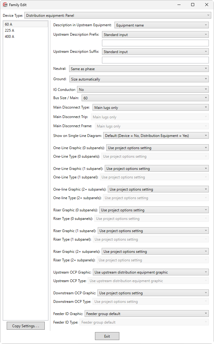
Distribution Equipment: Panel
These values are displayed when the Device Type ▾ is set to Distribution equipment: Panel.
-
Description in Upstream Equipment: ▾ The description for the distribution equipment that will appear in the circuit description of the upstream panel schedule, along with the Upstream Description Prefix and Upstream Description Suffix specified.
- Equipment name The description in the upstream panel schedule will be the same as the device name.
- Custom Enter a custom description in the field provided.
- Based on parameter The value for the specified parameter will be used. Press the button to select a parameter. See the Using Non-ElectroBIM Parameters for ElectroBIM Settings article in the knowledge base for more information..
-
Upstream Description Prefix: A prefix added to the start of the circuit description in the upstream equipment. The default description is the name of the family instance.
- Based on parameter The value for the specified parameter will be used. Press the button to select a parameter. See the Using Non-ElectroBIM Parameters for ElectroBIM Settings article in the knowledge base for more information..
-
Upstream Description Suffix: A suffix added to the end of the circuit description in the upstream equipment. The default description is the name of the family instance.
- Based on parameter The value for the specified parameter will be used. Press the button to select a parameter. See the Using Non-ElectroBIM Parameters for ElectroBIM Settings article in the knowledge base for more information..
-
Neutral: ▾ Sets the size of the neutral wire in the feeder.
- Same as phase The neutral wire will be the same size as the phase wires.
- Double phase The neutral wire will be two wires that are each the same size as the phase wires.
- None No neutral wire will be included in the feeder.
- Custom The neutral wire is set to the value you specify. Enter a value that corresponds to a wire size set in the Wire Sizes command in your project.
-
Ground: ▾ Sets the size of the ground wire in the feeder.
- Size automatically The ground wire is sized based upon the OCP Trip ▾ setting. If the distribution equipment is fed from a transformer, the service ground size is used. Otherwise, the equipment ground size is used.
- NEC 250.122 Equipment The ground wire is sized based upon the Ground Wire Size, Equipment ▾ setting for the wire ampacity specified in the Conductor ▾ field. See the Wire Ampacities command for more information.
- NEC 250.102 Service The ground wire is sized based upon the Ground Wire Size, Service ▾ setting for the wire ampacity specified in the Conductor ▾ field. See the Wire Ampacities command for more information.
- None No ground wire is included in the feeder.
- Custom The ground wire is set to the value you specify. Enter a value that corresponds to a wire size set in the Wire Sizes command in your project.
-
IG Conductor: ▾ Whether the feeder includes an isolated ground. If set to Yes, an isolated ground wire is included in the feeder callout.
-
Bus Size / Mains: ▾ The size of the bus.
- Specific ampacity The value is set to the specific size chosen from the list.
- Based on parameter The value for the specified parameter will be used. Press the button to select a parameter. See the Using Non-ElectroBIM Parameters for ElectroBIM Settings article in the knowledge base for more information..
- Set in instance The value is not set for the family type. The size of the bus can be set using the Bus Size / Mains ▾ field in the Panel Edit dialog box.
- Custom Enter a custom value in the field provided.
-
Main Disconnect Type: ▾ The type of disconnect for the device.
- Main Lugs Only The device does not have a disconnect.
- Breaker The device has a main disconnect breaker.
- Fused Switch The device has a main disconnect fused switch.
- Based on parameter The value for the specified parameter will be used. Press the button to select a parameter. See the Using Non-ElectroBIM Parameters for ElectroBIM Settings article in the knowledge base for more information..
- A parameter value of 0 will correspond to Main Lugs Only.
- A parameter value of 1 will correspond to Breaker.
- A parameter value of 2 will correspond to Fused Switch.
-
Main Disconnect Trip: ▾ The trip rating of the main disconnect breaker or fused switch.
- Same as bus amps The trip rating is the same as the Bus Size / Mains ▾ value.
- Based on parameter The value for the specified parameter will be used. Press the button to select a parameter. See the Using Non-ElectroBIM Parameters for ElectroBIM Settings article in the knowledge base for more information..
- Specific ampacity The trip rating is set to the specific size chosen from the list.
-
Main Disconnect Frame: ▾ The frame size of the main disconnect breaker or fused switch.
- Same as bus amps The frame size is the same as the Bus Size / Mains ▾ value.
- Based on parameter The value for the specified parameter will be used. Press the button to select a parameter. See the Using Non-ElectroBIM Parameters for ElectroBIM Settings article in the knowledge base for more information..
- Specific ampacity The frame size is set to the specific size chosen from the list.
-
Show on Single-Line Diagram: ▾ Whether the distribution equipment is inserted on the single-line diagram when using the Generate One-Line or Generate Riser commands, and whether it is displayed in the Insert Link and Copy Link commands. The default setting for distribution equipment is Yes.
-
One-Line Graphic (0 subpanels): ▾ The default graphic family used for the distribution equipment when it is inserted on a one-line diagram and has no downstream distribution equipment. The values in this list are based upon the Single-Line Diagram Device Graphics command.
- Use project options setting The Default panel graphic ▾ specified in the Generate One-Line Project Options for the project will be used.
-
One-Line Type (0 subpanels): ▾ The graphic type used for the distribution equipment. The values in this list are based upon the selected One-Line Graphic (0 subpanels) ▾.
-
One-Line Graphic (1 subpanel): ▾ The default graphic family used for the distribution equipment when it is inserted on a one-line diagram and has 1 downstream distribution equipment. The values in this list are based upon the Single-Line Diagram Device Graphics command.
- Use project options setting The Default panel graphic ▾ specified in the Generate One-Line Project Options for the project will be used.
-
One-Line Type (1 subpanel): ▾ The graphic type used for the distribution equipment. The values in this list are based upon the selected One-Line Graphic (1 subpanels) ▾.
-
One-Line Graphic (2+ subpanels): ▾ The default graphic family used for the distribution equipment when it is inserted on a one-line diagram and has 2 or more downstream distribution equipment. The values in this list are based upon the Single-Line Diagram Device Graphics command.
- Use project options setting The Default panel graphic ▾ specified in the Generate One-Line Project Options for the project will be used.
-
One-Line Type (2+ subpanels): ▾ The graphic type used for the distribution equipment. The values in this list are based upon the selected One-Line Graphic (2+ subpanels) ▾.
-
Riser Graphic (0 subpanels): ▾ The default graphic family used for the distribution equipment when it is inserted on a riser diagram and has no downstream distribution equipment. The values in this list are based upon the Single-Line Diagram Device Graphics command.
- Use project options setting The Default panel graphic ▾ specified in the Generate Riser Project Options for the project will be used.
-
Riser Type (0 subpanels): ▾ The graphic type used for the distribution equipment. The values in this list are based upon the selected Riser Graphic (0 subpanels) ▾.
-
Riser Graphic (1 subpanel): ▾ The default graphic family used for the distribution equipment when it is inserted on a riser diagram and has 1 downstream distribution equipment. The values in this list are based upon the Single-Line Diagram Device Graphics command.
- Use project options setting The Default panel graphic ▾ specified in the Generate Riser Project Options for the project will be used.
-
Riser Type (1 subpanel): ▾ The graphic type used for the distribution equipment. The values in this list are based upon the selected Riser Graphic (1 subpanel) ▾.
-
Riser Graphic (2+ subpanels): ▾ The default graphic family used for the distribution equipment when it is inserted on a riser diagram and has 2 or more downstream distribution equipment. The values in this list are based upon the Single-Line Diagram Device Graphics command.
- Use project options setting The Default panel graphic ▾ specified in the Generate Riser Project Options for the project will be used.
-
Riser Type (2+ subpanels): ▾ The graphic type used for the distribution equipment. The values in this list are based upon the selected Riser Graphic (2+ subpanels) ▾.
-
Upstream OCP Graphic: ▾ The graphic family used for the upstream OCP when the distribution equipment is inserted on the single-line diagram. The values in this list are based upon the Single-Line Diagram Feeder Graphics command.
- Use project options setting The Default OCP graphic ▾ specified in the Project Options command will be used.
- None No OCP graphic will be inserted.
-
Upstream OCP Type: ▾ The graphic type used for the upstream OCP. The values in this list are based upon the selected Upstream OCP Graphic ▾.
-
Downstream OCP Graphic: ▾ The graphic family used for the OCP when devices connected to the distribution equipment are first inserted on the single-line diagram. The values in this list are based upon the Single-Line Diagram Feeder Graphics command.
- Use project options setting The Default OCP graphic ▾ specified in the Project Options command will be used.
- None No OCP graphic will be inserted.
-
Downstream OCP Type: ▾ The graphic type used for the OCP. The values in this list are based upon the selected Downstream OCP Graphic ▾.
-
Feeder ID Graphic: ▾ The graphic family used for the feeder ID when the distribution equipment is inserted on the single-line diagram. The values in this list are based upon the Single-Line Diagram Feeder Graphics command.
- Feeder group default The feeder ID graphic set for the group in the Project Feeder ID Schedule will be used.
- None No feeder ID graphic will be inserted.
-
Feeder ID Type: ▾ The graphic type used for the feeder ID. The values in this list are based upon the selected Feeder ID Graphic ▾.
Distribution Equipment: Transformer
These values are displayed when the Device Type ▾ is set to Distribution equipment: Transformer.
![]()
-
Description in Upstream Equipment: ▾ The description for the distribution equipment that will appear in the circuit description of the upstream panel schedule, along with the Upstream Description Prefix and Upstream Description Suffix specified.
- Equipment name The description in the upstream panel schedule will be the same as the device name.
- Custom Enter a custom description in the field provided.
- Based on parameter The value for the specified parameter will be used. Press the button to select a parameter. See the Using Non-ElectroBIM Parameters for ElectroBIM Settings article in the knowledge base for more information..
-
Upstream Description Prefix: A prefix added to the start of the circuit description in the upstream equipment. The default description is the name of the family instance.
- Based on parameter The value for the specified parameter will be used. Press the button to select a parameter. See the Using Non-ElectroBIM Parameters for ElectroBIM Settings article in the knowledge base for more information..
-
Upstream Description Suffix: A suffix added to the end of the circuit description in the upstream equipment. The default description is the name of the family instance.
- Based on parameter The value for the specified parameter will be used. Press the button to select a parameter. See the Using Non-ElectroBIM Parameters for ElectroBIM Settings article in the knowledge base for more information..
-
Neutral: ▾ Sets the size of the neutral wire in the feeder.
- Same as phase The neutral wire will be the same size as the phase wires.
- Double phase The neutral wire will be two wires that are each the same size as the phase wires.
- None No neutral wire will be included in the feeder.
- Custom The neutral wire is set to the value you specify. Enter a value that corresponds to a wire size set in the Wire Sizes command in your project.
-
Ground: ▾ Sets the size of the ground wire in the feeder.
- Size automatically The ground wire is sized based upon the OCP Trip ▾ setting. If the distribution equipment is fed from a transformer, the service ground size is used. Otherwise, the equipment ground size is used.
- NEC 250.122 Equipment The ground wire is sized based upon the Ground Wire Size, Equipment ▾ setting for the wire ampacity specified in the Conductor ▾ field. See the Wire Ampacities command for more information.
- NEC 250.102 Service The ground wire is sized based upon the Ground Wire Size, Service ▾ setting for the wire ampacity specified in the Conductor ▾ field. See the Wire Ampacities command for more information.
- None No ground wire is included in the feeder.
- Custom The ground wire is set to the value you specify. Enter a value that corresponds to a wire size set in the Wire Sizes command in your project.
-
IG Conductor: ▾ Whether the feeder includes an isolated ground. If set to Yes, an isolated ground wire is included in the feeder callout.
-
Size: ▾ The size of the transformer in kVA.
- Specific size The value is set to the specific size chosen from the list.
- Based on parameter The value for the specified parameter will be used. Press the button to select a parameter. See the Using Non-ElectroBIM Parameters for ElectroBIM Settings article in the knowledge base for more information..
- Set in instance The value is not set for the family type. The size can be set using the Size ▾ field in the Panel Edit dialog box.
- Custom Enter a custom value in the field provided.
-
K-Factor Rating: ▾ The specific K-factor rating of the transformer for handling the harmonic content of the load.
- Specific rating The value is set to the specific rating chosen from the list.
- Based on parameter The value for the specified parameter will be used. Press the button to select a parameter. See the Using Non-ElectroBIM Parameters for ElectroBIM Settings article in the knowledge base for more information..
- Set in instance The value is not set for the family type. The K-factor rating can be set using the K-Factor Rating ▾ field in the Panel Edit dialog box.
- Custom Enter the K-factor rating in the field provided.
-
Impedance %: ▾ The impedance of the transformer for fault calculations and voltage drop calculations.
- Default A default transformer impedance is used based upon the kVA of the transformer. See the Fault Calculations section of the
Panel Edit command for more information. - Custom Enter the transformer impedance in the field provided. It can typically be obtained from the transformer manufacturer.
- Set in instance The value is not set for the family type. The transformer impedance can be set using the Transformer Impedance % ▾ field in the Panel Edit dialog box.
- Based on parameter The value for the specified parameter will be used. Press the button to select a parameter. See the Using Non-ElectroBIM Parameters for ElectroBIM Settings article in the knowledge base for more information..
- Default A default transformer impedance is used based upon the kVA of the transformer. See the Fault Calculations section of the
-
X/R Ratio: ▾ The X/R ratio of the transformer for fault calculations.
- Default A default X/R ratio of 5 is used for the transformer.
- Custom Enter the X/R ratio in the field provided. It can typically be obtained from the transformer manufacturer.
- Set in instance The value is not set for the family type. The X/R ratio can be set using the Transformer X/R Ratio ▾ field in the Panel Edit dialog box.
- Based on parameter The value for the specified parameter will be used. Press the button to select a parameter. See the Using Non-ElectroBIM Parameters for ElectroBIM Settings article in the knowledge base for more information..
-
Show on Single-Line Diagram: ▾ Whether the distribution equipment is inserted on the single-line diagram when using the Generate One-Line or Generate Riser commands, and whether it is displayed in the Insert Link and Copy Link commands. The default setting for distribution equipment is Yes.
-
One-Line Graphic (0 or 1 subpanels): ▾ The default graphic family used for the distribution equipment when it is inserted on a one-line diagram and has 0 or 1 downstream distribution equipment. The values in this list are based upon the Single-Line Diagram Device Graphics command.
- Use project options setting The Default panel graphic ▾ specified in the Generate One-Line Project Options for the project will be used.
-
One-Line Type (0 or 1 subpanels): ▾ The graphic type used for the distribution equipment. The values in this list are based upon the selected One-Line Graphic (0 or 1 subpanels) ▾.
-
One-Line Graphic (2+ subpanels): ▾ The default graphic family used for the distribution equipment when it is inserted on a one-line diagram and has 2 or more downstream distribution equipment. The values in this list are based upon the Single-Line Diagram Device Graphics command.
- Use project options setting The Default panel graphic ▾ specified in the Generate One-Line Project Options for the project will be used.
-
One-Line Type (2+ subpanels): ▾ The graphic type used for the distribution equipment. The values in this list are based upon the selected One-Line Graphic (2+ subpanels) ▾.
-
Riser Graphic (0 or 1 subpanels): ▾ The default graphic family used for the distribution equipment when it is inserted on a riser diagram and has 0 or 1 downstream distribution equipment. The values in this list are based upon the Single-Line Diagram Device Graphics command.
- Use project options setting The Default panel graphic ▾ specified in the Generate Riser Project Options for the project will be used.
-
Riser Type (0 or 1 subpanels): ▾ The graphic type used for the distribution equipment. The values in this list are based upon the selected Riser Graphic (0 or 1 subpanels) ▾.
-
Riser Graphic (2+ subpanels): ▾ The default graphic family used for the distribution equipment when it is inserted on a riser diagram and has 2 or more downstream distribution equipment. The values in this list are based upon the Single-Line Diagram Device Graphics command.
- Use project options setting The Default panel graphic ▾ specified in the Generate Riser Project Options for the project will be used.
-
Riser Type (2+ subpanels): ▾ The graphic type used for the distribution equipment. The values in this list are based upon the selected Riser Graphic (2+ subpanels) ▾.
-
Upstream OCP Graphic: ▾ The graphic family used for the upstream OCP when the distribution equipment is inserted on the single-line diagram. The values in this list are based upon the Single-Line Diagram Feeder Graphics command.
- Use project options setting The Default OCP graphic ▾ specified in the Project Options command will be used.
- None No OCP graphic will be inserted.
-
Upstream OCP Type: ▾ The graphic type used for the upstream OCP. The values in this list are based upon the selected Upstream OCP Graphic ▾.
-
Downstream OCP Graphic: ▾ The graphic family used for the OCP when devices connected to the distribution equipment are first inserted on the single-line diagram. The values in this list are based upon the Single-Line Diagram Feeder Graphics command.
- Use project options setting The Default OCP graphic ▾ specified in the Project Options command will be used.
- None No OCP graphic will be inserted.
-
Downstream OCP Type: ▾ The graphic type used for the OCP. The values in this list are based upon the selected Downstream OCP Graphic ▾.
-
Feeder ID Graphic: ▾ The graphic family used for the feeder ID when the distribution equipment is inserted on the single-line diagram. The values in this list are based upon the Single-Line Diagram Feeder Graphics command.
- Feeder group default The feeder ID graphic set for the group in the Project Feeder ID Schedule will be used.
- None No feeder ID graphic will be inserted.
-
Feeder ID Type: ▾ The graphic type used for the feeder ID. The values in this list are based upon the selected Feeder ID Graphic ▾.