Circuit Edit

Allows you to set information used for sizing branch circuits.
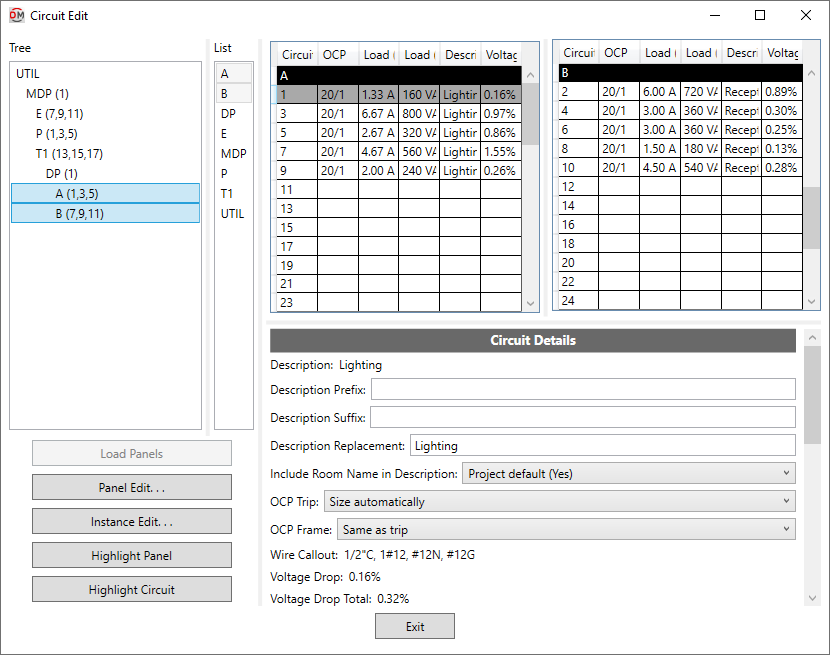
Opens the Circuit Edit dialog box:
Circuit Edit Dialog Box
The wire size values that are calculated are stored in shared parameters on the circuits. These shared parameters can be displayed in your panel schedule in addition to or instead of built-in Revit parameters. See the Modifying Panel Schedules section in the tutorial for more information.
Distribution Equipment Tree & List
-
Tree / List ☰ All of the distribution equipment in your project. They are organized based upon the connections in the model, and listed alphabetically by device name.
You can select multiple equipment in the tree and list using the SHIFT or CTRL key.
-
If you run the
Circuit Edit command with one or more distribution equipment or circuited devices selected, only the selected equipment will appear in the Tree / List ☰. Press this button to display the rest of the distribution equipment in the model. -
Press this button to close this dialog box and run the Panel Edit command with the selected distribution equipment active.
-
Press this button to close this dialog box and run the Instance Edit command with the instances on the selected circuit active.
-
Press this button to highlight the selected distribution equipment in the model or on the single-line diagram, similar to the Revit Highlight in Model command. If the device exists on multiple views, you will be prompted to specify a view.
-
Press this button to highlight all of the devices on the selected circuit in the model or on the single-line diagram, similar to the Revit Highlight in Model command. If the devices exist on multiple views, you will be prompted to specify a view.
Circuit Tables
This section lists all of the circuits on the selected distribution equipment. If the distribution equipment is a panel with odd and even sides, the odd circuits are listed on the left and the even circuits are listed on the right. Otherwise, all of the circuits are listed on the left and the grid on the right will be blank.
You can select multiple circuits using the SHIFT or CTRL key.
-
Description The description for the circuit as it will appear on the distribution equipment schedule. Changes made to this field will be reflected in the Description field in the Circuit Details section of the dialog box. Depending upon the change made to the description, the Description Prefix, Description Suffix, or Description Replacement field will also be affected.
warningIf Circuit description method ▾ in the Project Options command is set to Use Revit circuit descriptions, the circuit description cannot be changed in this dialog box. This field will be disabled.
Circuit Details
This section displays information about the selected circuit.
When a feeder to a downstream piece of distribution equipment is selected, basic information about the feeder is displayed. To make changes to the feeder, use the
When a space is selected that has nothing connected to it, you will not be able to make any changes.
When a branch circuit is selected, changes can be made to the circuit using the fields described below. If multiple circuits are selected, fields that have different values across the selected circuits will display <Varies>.
-
Description: The description for the circuit as it will appear on the distribution equipment schedule. This value is added before any other descriptions on the circuit from connected devices.
warningIf Circuit description method ▾ in the Project Options command is set to Use Revit circuit descriptions, the circuit description cannot be changed in this dialog box.
The Description value will be followed by (Controlled by Revit). The Description Prefix, Description Suffix, Description Replacement, and Include Room Name in Description ▾ fields will not be available.
-
Description Prefix: Text that will be added to the front of the circuit description.
-
Description Suffix: Text that will be added to the end of the circuit description. This value will be added before the room names if they are included.
-
Description Replacement: Text that will completely replace the circuit description. The circuit description on the device, Description Prefix, and Description Suffix will not be used. The room name will not be included.
-
Include Room Name in Description: ▾ Whether the rooms served by the circuit are included in the circuit description.
warningThe list of rooms may be different from what Revit would show. Revit only shows a single room name if multiple rooms are on the circuit.
- Project default This setting is based upon the Include room names in circuit descriptions ▾ option in the Project Options command.
- Yes Room names will be included at the end of the circuit description. The names of each area containing devices on this circuit will be listed.
- No Room names will not be included in the circuit description.
-
OCP Trip: ▾ Sets the size of the OCP for the branch circuit. Used to set the Rating value of the branch circuit.
- Size automatically The OCP is sized to 125% of the connected load.
- None No OCP is used for the branch circuit. The Rating value is set to 0.
- Specific ampacity The OCP is sized to match the ampacity chosen from the list.
-
OCP Frame: ▾ Sets the size of the frame for the branch circuit. Used to set the Frame value of the branch circuit.
- Same as trip The frame is sized to match the OCP Trip ▾ value.
- None No frame is used for the branch circuit. The Frame value is set to 0.
- Specific ampacity: The frame is sized to match the ampacity chosen from the list.
-
Wire Callout: The callout for the branch circuit, listing all of the wire sizes.
-
Voltage Drop: The voltage drop on the branch circuit. This value is based upon the load on the circuit, the wire size, and the circuit length. The calculation assumes the whole load is located at a distance equal to the Actual Length away from the distribution equipment.
-
Voltage Drop Total: The cumulative voltage drop from the utility to the branch circuit.
-
Fault at Device: The fault at the device connected to the branch circuit including both utility fault and motor fault. The fault is calculated at a distance equal to the Actual Length away from the distribution equipment.
-
Conductor: ▾ Sets the size of the conductors.
- Default The conductors are sized based upon the OCP Trip ▾ setting according to the active sizing option in the Wire Ampacities command.
- Upsized The conductors are first sized based upon the OCP Trip ▾ setting according to the active sizing option in the Wire Ampacities command. They are then upsized to reduce voltage drop based upon settings in the Project Options command.
- Sizing option The conductors are sized based upon the OCP Trip ▾ setting according to the sizing option chosen from the list.
- Custom The Wire Callout, Neutral ▾, Ground ▾, Conduit ▾, Conduit Fill, and Ambient Temperature ▾ fields will be disabled. The following fields will be provided:
- Custom Callout: Enter the callout for the branch circuit.
- Custom Feeder ID: Enter the feeder ID to be used on the single-line diagram for the branch circuit.
- Custom X: Enter the reactance per 1000' for the branch circuit.
- Custom R: Enter the resistance per 1000' for the branch circuit.
- None The branch circuit does not have any wires. The Wire Callout will be blank.
- Specific ampacity The conductors are sized to match the wire ampacity chosen from the list.
-
Neutral: ▾ Sets the size of the neutral wire.
- Same as phase The neutral wire is the same size as the phase wires specified in the Conductor ▾ field.
- Double phase The neutral wire uses two wires that are each twice the size of the phase wires specified in the Conductor ▾ field. The ampacity of the conductor wires will be derated 80% based upon NEC Table 310.15(C)(1).
- None No neutral wire is included. See the Neutrals article in the knowledge base for more information about this option.
- Specific wire size The neutral wire is sized to match the wire size chosen from the list.
-
Ground: ▾ Sets the size of the ground wire.
- Size automatically The ground wire is sized automatically based upon the OCP Trip ▾ setting and the Ground Wire Size, Equipment ▾ ground setting for the ampacity specified. See the Wire Ampacities command for more information.
- NEC 250.122 Equipment The ground wire is sized based upon the Ground Wire Size, Equipment ▾ setting for the wire ampacity specified in the Conductor ▾ field. See the Wire Ampacities command for more information.
- NEC 250.102 Service The ground wire is sized based upon the Ground Wire Size, Service ▾ setting for the wire ampacity specified in the Conductor ▾ field. See the Wire Ampacities command for more information.
- None No ground wire is included.
- Specific wire size The ground wire is sized to match the wire size chosen from the list.
-
Conduit: ▾ Sets the size of the conduit.
- Size automatically The conduit is sized automatically based upon the wires. All conduits are sized using a 40% conduit fill per NEC Table 1.
- None No conduit is included.
- Specific conduit size The conduit is sized to match the conduit size chosen from the list.
-
Conduit Fill: The conduit fill percentage for the branch circuit wire.
-
Ambient Temperature: ▾ The ambient temperature at the location of the branch circuit.
- Default The branch circuit will be sized based upon the Ambient temperature option set in the Project Options command.
- Custom Enter the ambient temperature in °C in the field provided. Select this option to size the branch circuit based upon the outdoor temperature or NEC 310.15(B)(2).
-
Circuit Length: ▾ The average distance from the distribution equipment to the devices on the branch circuit.
- Default The length is calculated based upon the Branch Circuit Length Calculation Method ▾ setting in the distribution equipment in the Panel Edit command.
- Straight line The length is calculated based upon the straight line distance between the distribution equipment and the devices on the circuit. This calculation approximates lengths for wires running directly between devices, typically underground.
- Right angles The length is calculated based upon the distance along the axes of the building between the distribution equipment and the devices on the circuit. This calculation approximates lengths for wires running along the walls of the building.
- Revit calculated length The length is based upon the distance that Revit calculates using the Circuit Path feature.
- Fixed Enter the length of the branch circuit in the field provided.
-
Actual Length: The total calculated length of the branch circuit. If Circuit Length ▾ is set to Fixed, this field displays the sum of the Circuit Length ▾ value and any wire make-up. Otherwise, this field displays the same value as Circuit Length ▾.
-
Building Angle: The orientation of the building used when Circuit Length ▾ is set to Right angles. See the How Building Angle Affects Calculations article in the knowledge base for more information about this setting.
-
Wire Make-up: ▾ Additional length of wire added to automatically calculated branch circuit lengths to represent make-up in the field.
- Default The length is based upon the Branch Circuit Wire Make-Up ▾ setting in the distribution equipment in the Panel Edit command.
- Custom Enter a custom length in the field provided.
-
Add Wire Make-Up for Each Device: ▾ Whether the length specified in Wire Make-up ▾ is added for each device on the circuit.
- Default The setting is based upon the Add Branch Circuit Wire Make-Up for Each Device ▾ setting in the distribution equipment in the Panel Edit command.
- Yes The length is added for each device on the circuit.
- No The length is added once, regardless of the number of devices on the circuit.
Circuit description method: Sets whether the Description value can be controlled in this dialog box.
Include room names in circuit descriptions: Sets the default for the Include Room Name in Description ▾ setting.
Display neutral wire count separately from phase wire count: Sets whether the neutral wire is displayed separately in the Wire Callout.
Conduit location: Sets where the conduit size is displayed in the Wire Callout.
There are several options that affect whether and how the wires specified in the Conductor ▾ field can be upsized to reduce voltage drop. See the Voltage Drop Project Options section for more information.
Ambient temperature: Sets the default for the Ambient Temperature ▾ field.
Building angle: Sets the default value for the Building Angle field.