Panel Edit

Allows you to view and edit the information for distribution equipment in your project.
If you are in a drafting view, you will be prompted to specify a distribution equipment in the view or press ESC.
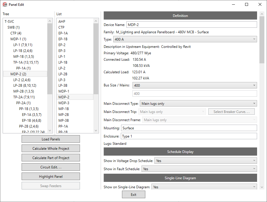
Opens the Panel Edit dialog box:
Panel Edit Dialog Box
-
Tree / List ☰ All of the distribution equipment in your project. They are organized based upon the connections in the model, and listed alphabetically by Device Name.
You can select multiple equipment in the tree and list using the SHIFT or CTRL key. Only fields shared by all of the selected equipment will be shown. Fields that have different values across the selected equipment will display <Varies>.
-
If you run the
Panel Edit command with one or more distribution equipment selected, only the selected equipment will appear in the Tree / List ☰. Press this button to display the rest of the distribution equipment in the model. -
Press this button to run the Calculate Whole Project command.
-
Press this button to run the Calculate Part of Project command beginning at the selected distribution equipment.
-
Press this button to close this dialog box and run the Circuit Edit command with the selected distribution equipment active.
-
Press this button to highlight the selected distribution equipment in the model or on the single-line diagram, similar to the Revit Highlight in Model command. If the device exists on multiple views, you will be prompted to specify a view.
-
This button is enabled when you select a piece of distribution equipment with two feeders. The two feeders are arbitrarily assigned to be feeder 1 or feeder 2. Feeder 1 is considered the main feeder for the equipment and should lead back to the utility. Feeder 2 should be used for the emergency or bypass feeder. Press this button to change which feeder is assigned which number.
Definition
-
Device Name: The name of the distribution equipment. This is the same value as the Revit Panel Name parameter. Changing the Device Name in this dialog box will also change the Panel Name. It will also update the name of the panel schedule associated with this distribution equipment.
-
Family: The family of the distribution equipment. This value is read-only and cannot be changed in this dialog box.
-
Type: ▾ The family type of the distribution equipment. The types in the list are based upon the distribution equipment Family.
-
Description in Upstream Equipment: ▾ The description for the distribution equipment that will appear in the circuit description of the upstream panel schedule.
- Default The description in the upstream panel schedule will be the same as the device name, along with the Upstream Description Prefix and Upstream Description Suffix specified in the Family Edit command.
- Custom Enter a custom description in the field provided.
- Based on parameter The value for the specified parameter will be used. Press the button to select a parameter. See the Using Non-ElectroBIM Parameters for ElectroBIM Settings article in the knowledge base for more information.
- Controlled by Revit If Circuit description method ▾ in the Project Options command is set to Use Revit circuit descriptions, this field is disabled.
-
Primary Voltage: The primary voltage of the distribution equipment. This is the same value as the Revit Distribution System parameter.
tipThis value cannot be changed in the Panel Edit dialog box. Use the standard Revit interface to change the Distribution System.
-
Secondary Voltage: The secondary voltage of the distribution equipment. This is the same value as the Revit Secondary Distribution System parameter. This field is only displayed for transformers.
tipThis value cannot be changed in the Panel Edit dialog box. Use the standard Revit interface to change the Secondary Distribution System.
-
Connected Load: The total connected load on the distribution equipment. These fields are the same values as the Revit Total Connected and Total Connected Current parameters.
- Primary/Secondary: The total connected current at the primary and secondary voltages on the distribution equipment. The Secondary field is the same value as the Revit Total Connected Current parameter.These fields are only displayed for transformers.
-
Calculated Load: The total calculated demand load on the distribution equipment. These fields are the same values as the Revit Total Estimated Demand and Total Estimated Demand Current parameters.
- Primary/Secondary: The total calculated demand current at the primary and secondary voltages on the distribution equipment. The Secondary field is the same value as the Revit Total Estimated Demand Current parameter. These fields are only displayed for transformers.
-
Bus Size / Mains: ▾ The size of the bus. This field is the same value as the Revit Mains parameter that can be set in the Electrical - Circuiting section of the Properties panel for distribution equipment. This field is only displayed for panels and switchboards.
- Specific ampacity The mains value is set to the specific size chosen from the list.
- Custom Enter a custom mains value in the field provided.
tipThis value can be set in the family definition using the Family Edit command. If it is, the value cannot be changed in the instance in the project.
-
Main Disconnect Type: ▾ The type of disconnect for the device. This field is only displayed for panels and switchboards.
- Family default The type has been set in the family using the Family Edit command. The value from the family will be used.
- Main Lugs Only The device does not have a disconnect.
- Breaker The device has a main disconnect breaker.
- Fused Switch The device has a main disconnect fused switch.
- Based on parameter The value for the specified parameter will be used. Press the button to select a parameter. See the Using Non-ElectroBIM Parameters for ElectroBIM Settings article in the knowledge base for more information..
A parameter value of 0 will correspond to Main Lugs Only.
A parameter value of 1 will correspond to Breaker.
A parameter value of 2 will correspond to Fused Switch.
-
Main Disconnect Trip: ▾ The trip rating of the main disconnect breaker or fused switch. This field is only displayed for panels and switchboards.
- Family default The trip rating has been set in the family using the Family Edit command. The value from the family will be used.
- Same as bus amps The trip rating is the same as the Bus Size / Mains ▾ value.
- Based on parameter The value for the specified parameter will be used. Press the button to select a parameter. See the Using Non-ElectroBIM Parameters for ElectroBIM Settings article in the knowledge base for more information..
- Specific ampacity The trip rating is set to the specific size chosen from the list.
-
Press this button to configure the curve for the main disconnect breaker or fused switch. The OCP Device Settings dialog box will appear. If Main Disconnect Type ▾ is set to Main Lugs Only, this button is disabled. This button is only displayed for panels and switchboards.
-
Main Disconnect Frame: ▾ The frame size of the main disconnect breaker or fused switch. This field is only displayed for panels and switchboards.
- Family default The frame size has been set in the family using the Family Edit command. The value from the family will be used.
- Same as bus amps The frame size is the same as the Bus Size / Mains ▾ value.
- Based on parameter The value for the specified parameter will be used. Press the button to select a parameter. See the Using Non-ElectroBIM Parameters for ElectroBIM Settings article in the knowledge base for more information..
- Specific ampacity The frame size is set to the specific size chosen from the list.
-
Mounting: How the device is mounted. This field is the same value as the Revit Mounting parameter that can be set in the General section of the Properties panel for distribution equipment.
-
Enclosure: The enclosure for the device. This field is the same value as the Revit Enclosure parameter that can be set in the General section of the Properties panel for distribution equipment.
-
Lugs: The lugs used on the distribution equipment. This setting controls the type of connection you can make on downstream distribution equipment. The single-line diagram graphics for the bus bar are also affected by this setting.
This value cannot be set in this dialog box. The value displayed is based upon the device definition in Revit.
- Standard The Revit Feed Through Lugs and SubFeed Lugs parameters are disabled.
- Feed Through The Revit Feed Through Lugs parameter is enabled.
- Double The Revit Feed Through Lugs and SubFeed Lugs parameters are enabled.
Transformer Only Fields
-
Size: ▾ The size of the transformer in kVA. Select the size from the list or manually enter the value. The sizes in the list are based upon the Transformer OCP Sizes command.
tipThis value can be set in the family definition using the Family Edit command. If it is, the value cannot be changed in the instance in the project.
-
K-Factor Rating: ▾ The specific K-factor rating of the transformer for handling the harmonic content of the load.
tipThis value can be set in the family definition using the Family Edit command. If it is, the value cannot be changed in the instance in the project.
Schedule Display
-
Show in Voltage Drop Schedule: ▾ Whether the distribution equipment is displayed in the voltage drop schedule.
-
Show in Fault Schedule: ▾ Whether the distribution equipment is displayed in the fault current schedule.
Single-Line Diagram
-
Show on Single-Line Diagram: ▾ Whether the distribution equipment is inserted on the single-line diagram when using the Generate One-Line, Generate Riser, or Export to AutoCAD commands, and whether it is displayed in the Insert Link and Copy Link commands. The default setting for distribution equipment is Yes.
-
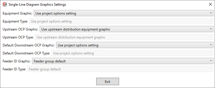
Press this button to open the Single-Line Diagram Graphics Settings dialog box. Use this dialog box to manage the graphics that represent the distribution equipment on the single-line diagram.
-
Equipment Graphic: ▾ The default graphic family used for the distribution equipment when it is inserted on the single-line diagram. The values in this list are based upon the Single-Line Diagram Device Graphics command.
- Family default The Single-Line Graphic ▾ specified in the distribution equipment family will be used.
- Use project options setting The Default panel graphic ▾ or Default transformer graphic ▾ specified in the Generate One-Line Project Options or Generate Riser Project Options will be used.
-
Equipment Type: ▾ The graphic type used for the distribution equipment. The values in this list are based upon the selected Equipment Graphic ▾.
-
Upstream OCP Graphic: ▾ The graphic family used for the upstream OCP when the distribution equipment is inserted on the single-line diagram. The values in this list are based upon the Single-Line Diagram Feeder Graphics command.
- Family default The Upstream OCP Graphic ▾ specified in the distribution equipment family will be used.
- Use upstream distribution equipment graphic The Default Downstream OCP Graphic ▾ and Default Downstream OCP Type ▾ specified in the upstream distribution equipment will be used.
- None No OCP graphic will be inserted.
-
Upstream OCP Type: ▾ The graphic type used for the upstream OCP. The values in this list are based upon the selected Upstream OCP Graphic ▾.
-
Default Downstream OCP Graphic: ▾ The graphic family used for the OCP when devices connected to the distribution equipment are first inserted on the single-line diagram. The values in this list are based upon the Single-Line Diagram Feeder Graphics command.
- Family default The Downstream OCP Graphic ▾ specified in the distribution equipment family will be used.
- Use project options setting The Default OCP graphic ▾ specified in the Project Options command will be used.
- None No OCP graphic will be inserted.
-
Default Downstream OCP Type: ▾ The graphic type used for the OCP. The values in this list are based upon the selected Default Downstream OCP Graphic ▾.
-
Feeder ID Graphic: ▾ The graphic family used for the feeder ID when the distribution equipment is inserted on the single-line diagram. The values in this list are based upon the Single-Line Diagram Feeder Graphics command.
- Family default The Feeder ID Graphic ▾ specified in the distribution equipment family will be used.
- Feeder group default The feeder ID graphic specified for the group in the Project Feeder ID Schedule will be used.
- None No feeder ID graphic will be inserted.
-
Feeder ID Type: ▾ The graphic type used for the feeder ID. The values in this list are based upon the selected Feeder ID Graphic ▾.
-
Default OCP graphic / type: Sets the project defaults for the Default Downstream OCP Graphic ▾ and Default Downstream OCP Type ▾ fields.
(One-line) Default panel / transformer graphic / type: / (Riser) Default panel / transformer graphic / type: Sets the project defaults for the Equipment Graphic ▾ and Equipment Type ▾ fields.
Upstream Connection
-
OCP Trip: ▾ The trip rating of the OCP in the device upstream of the distribution equipment. Used to set the Rating value of the connected circuit.
- Same as main disconnect or bus size / none if lugs The OCP is sized to match the Bus Size / Mains ▾ value, or the Main Disconnect Trip ▾ value if it is set. If the upstream connection is to a transformer or lugs, no OCP will be used and the Rating value of the connected electrical system will be set to 0. This setting is available for panels and switchboards.
- Same as main disconnect or bus size / breaker if lugs The OCP is sized to match the Bus Size / Mains ▾ value, including when the upstream connection is to a transformer or lugs. This setting is available for panels and switchboards.
- Size to match kVA The OCP is sized to match the Size ▾ field. This setting is available for transformers.
- Lugs or N/A There is no OCP for this device. The Rating value of the connected electrical system is set to 0.
- Based on parameter The value for the specified parameter will be used. Press the button to select a parameter. See the Using Non-ElectroBIM Parameters for ElectroBIM Settings article in the knowledge base for more information..
- Specific ampacity The OCP is set to the specific size chosen from the list.
-
Press this button to configure the curve for the upstream OCP. The OCP Device Settings dialog box will appear. If OCP Trip ▾ is set to Lugs or N/A, this button is disabled.
-
OCP Frame: ▾ The frame size of the OCP in the device upstream of the distribution equipment. Used to set the Frame value of the connected circuit.
- Same as main disconnect or bus size The frame is sized to match the Bus Size / Mains ▾ value, or the Main Disconnect Trip ▾ value if it is set. This setting is available for panels and switchboards.
- Size to match kVA The frame is sized to match the Size ▾ field. This setting is available for transformers.
- Based on parameter The value for the specified parameter will be used. Press the button to select a parameter. See the Using Non-ElectroBIM Parameters for ElectroBIM Settings article in the knowledge base for more information..
- Specific ampacity The frame size is set to the specific size chosen from the list.
Feeder
-
Fed From: The upstream distribution equipment to which this distribution equipment is connected.
-
Callout: The callout for the feeder, listing all of the wire sizes.
-
Voltage Drop from Upstream Equipment: The voltage drop in the feeder to this distribution equipment.
-
Voltage Drop from Utility: The cumulative voltage drop from the utility to this distribution equipment.
-
Conductor: ▾ The ampacity of the feeder conductors.
- Default The conductors are sized based upon the OCP Trip ▾ setting according to the active sizing option in the Wire Ampacities command.
- Upsized The conductors are first sized based upon the OCP Trip ▾ setting according to the active sizing option in the Wire Ampacities command. They are then upsized to reduce voltage drop based upon settings in the Project Options command.
- Sizing option The conductors are sized based upon the OCP Trip ▾ setting according to the sizing option chosen from the list.
- Custom The Callout, Neutral ▾, Ground ▾, IG Conductor ▾, Conduit ▾, Conduit Fill, and Ambient Temperature ▾ fields will be disabled. The following fields will be provided:
- Callout: Enter the callout for the feeder.
- Conduit: ▾ Sets the conduit size that is exported when using the EVOLVE Export command. This value is not otherwise used.
- Parallel Runs: Sets the number of parallel runs that is exported when using the EVOLVE Export command. This value is not otherwise used.
- Feeder ID: Enter the feeder ID to be used on the single-line diagram for the feeder.
- X: Enter the reactance per 1000' for the feeder.
- R: Enter the resistance per 1000' for the feeder.
- None There is no feeder to this distribution equipment. The Callout will be blank.
- Specific ampacity The conductors are sized to match the wire ampacity chosen from the list.
-
Neutral: ▾ Sets the size of the neutral wire in the feeder.
- Family default The neutral size has been set in the family using the Family Edit command. The value from the family will be used.
- Same as phase The neutral wire is the same size as the phase wires specified in the Conductor ▾ field.
- Double phase The neutral wire uses two wires that are each the size of the phase wires specified in the Conductor ▾ field. The ampacity of the conductor wires will be derated to 80% based upon NEC Table 310.15(C)(1).
- None No neutral wire is included in the feeder. See the Neutrals article in the knowledge base for more information about this option.
- Specific wire size The neutral wire is sized to match the wire size chosen from the list.
-
Ground: ▾ Sets the size of the ground wire in the feeder.
- Family default The ground size has been set in the family using the Family Edit command. The value from the family will be used.
- Size automatically The ground wire is sized based upon the OCP Trip ▾ setting. If the distribution equipment is fed from a transformer, the service ground size is used. Otherwise, the equipment ground size is used.
- NEC 250.122 Equipment The ground wire is sized based upon the Ground Wire Size, Equipment ▾ setting for the wire ampacity specified in the Conductor ▾ field. See the Wire Ampacities command for more information.
- NEC 250.102 Service The ground wire is sized based upon the Ground Wire Size, Service ▾ setting for the wire ampacity specified in the Conductor ▾ field. See the Wire Ampacities command for more information.
- None No ground wire is included in the feeder.
- Specific wire size The ground wire is sized to match the wire size chosen from the list.
-
IG Conductor: ▾ Whether the feeder includes an isolated ground.
- Family default The need for an isolated ground has been set in the family using the Family Edit command. The value from the family will be used.
- Yes An isolated ground will be included in the feeder.
- No An isolated ground will not be included in the feeder.
-
Conduit: ▾ Sets the size of the conduit for the feeder.
- Size automatically The conduit is sized automatically based upon the wires in the feeder. All conduits are sized using a 40% conduit fill per NEC Table 1.
- None No conduit is included for the feeder.
- Specific conduit size The conduit is sized to match the conduit size chosen from the list.
-
Conduit Fill: The conduit fill percentage for the feeder.
-
Ambient Temperature: ▾ The ambient temperature at the location of the feeder.
- Default The feeder will be sized based upon the Ambient temperature option set in the Project Options command.
- Custom Enter the ambient temperature in °C in the field provided. Select this option to size the feeder based upon the outdoor temperature or NEC 310.15(B)(2).
-
Length: ▾ The length of the feeder.
- Default The length is calculated using the Downstream Feeder Length Calculation Method ▾ option set in the upstream distribution equipment.
- Straight line The length is calculated based upon the straight line distance between the distribution equipment and upstream distribution equipment. This calculation approximates lengths for wires running directly between devices, typically underground.
- Right angles The length is calculated based upon the distance along the axes of the building between the distribution equipment and upstream distribution equipment. This calculation approximates lengths for wires running along the walls of the building.
- Revit calculated length The feeder length is based upon the distance that Revit calculates using the Circuit Path feature.
- Fixed Enter the length of the feeder in the field provided.
-
Building Angle: The orientation of the building used when Length ▾ is set to Right angles. See the How Building Angle Affects Calculations article in the knowledge base for more information about this setting.
-
Wire Make-Up: ▾ Additional length of wire added to automatically calculated feeder lengths to represent make-up in the field. If Length ▾ is set to Fixed, this field is disabled.
- Default The length is based upon the Feeder wire make-up length option set in the Project Options command.
- Custom Enter a custom length in the field provided.
-
Conduit Run Id: The ID that corresponds to the feeder when using the EVOLVE Export and EVOLVE Import commands.
Display neutral wire count separately from phase wire count: Sets whether the neutral wire is displayed separately in the Callout.
Conduit location: Sets where the conduit size is displayed in the Callout.
There are several options that affect whether and how the wires specified in the Conductor ▾ field can be upsized to reduce voltage drop. See the Voltage Drop Project Options section for more information.
Ambient temperature: Sets the default for the Ambient Temperature ▾ field.
Building angle: Sets the default value for the Building Angle field.
Feeder wire make-up length: Sets the default value for the Wire Make-Up ▾ field.
Upstream Connection 2
If the distribution equipment has two feeders, the settings for the second upstream connection are listed in this section. The settings are the same as the ones available in the Upstream Connection section described above.
Feeder 2
If the distribution equipment has two feeders, the settings for the second feeder are listed in this section. The settings are the same as the ones available in the Feeder section described above.
Circuit Lengths
-
Downstream Feeder Length Calculation Method: ▾ How the lengths are calculated for feeders between this distribution equipment and distribution equipment connected to it.
- Default The lengths are calculated based upon the Feeder length calculation method ▾ option set in the Project Options command.
- Straight line The lengths are calculated based upon the straight line distance between the distribution equipment and other distribution equipment connected to it. This calculation approximates lengths for wires running directly between devices, typically underground.
- Right angles The lengths are calculated based upon the distance along the axes of the building between the distribution equipment and other distribution equipment connected to it. This calculation approximates lengths for wires running along the walls of the building.
- Revit calculated length The lengths are based upon the distance that Revit calculates using the Circuit Path feature.
-
Branch Circuit Length Calculation Method: ▾ How the lengths are calculated for branch circuits between this distribution equipment and devices connected to it.
- Default The lengths are calculated based upon the Branch circuit length calculation method ▾ option set in the Project Options command.
- Straight line The lengths are calculated based upon the straight line distance between the distribution equipment and devices connected to it. This calculation approximates lengths for wires running directly between devices, typically underground.
- Right angles The lengths are calculated based upon the distance along the axes of the building between the distribution equipment and devices connected to it. This calculation approximates lengths for wires running along the walls of the building.
- Revit calculated length The lengths are based upon the distance that Revit calculates using the Circuit Path feature.
-
Building Angle: The orientation of the building used when the Downstream Feeder Length Calculation Method ▾ or Branch Circuit Length Calculation Method ▾ is set to Right angles. See the How Building Angle Affects Calculations article in the knowledge base for more information about this setting.
-
Branch Circuit Wire Make-Up: ▾ Additional length of wire added to automatically calculated branch circuit lengths to represent make-up in the field.
- Default The length is based upon the Branch circuit wire make-up length option set in the Project Options command.
- Custom Enter a custom length in the field provided.
-
Add Branch Circuit Wire Make-Up for Each Device: ▾ Whether the length specified in Branch Circuit Wire Make-Up ▾ is added for each device on the circuit.
- Default The setting is based upon the Add branch circuit wire make-up for each device ▾ option set in the Project Options command.
- Yes The length is added for each device on the circuit.
- No The length is added once, regardless of the number of devices on the circuit.
Feeder length calculation method: Sets the default for the Downstream Feeder Length Calculation Method ▾ field.
Branch circuit length calculation method: Sets the default for the Branch Circuit Length Calculation Method ▾ field.
Building angle: Sets the default value for the Building Angle field.
Branch circuit wire make-up length: Sets the default value for the Branch Circuit Wire Make-Up ▾ field.
Add branch circuit wire make-up for each device: Sets the default value for the Add Branch Circuit Wire Make-Up For Each Device ▾ field.
Fault Calculations
-
Total Fault Including Motors: The total fault at the distribution equipment including both utility fault and motor fault. This field is for informational purposes to be used while defining the distribution equipment. To set a specific fault value, use the Utility Fault at Device ▾ field.
-
Utility Fault at Device: ▾ The fault at the distribution equipment from the utility. Motor fault values are not included in this value.
- Calculated The fault at the distribution equipment is calculated based upon the model.
- Fixed Enter the fault at the distribution equipment in the field provided.
-
Utility Fault X/R Ratio: The X/R ratio of the utility fault at the device. If Utility Fault at Device ▾ is set to Fixed, you can manually set this value.
-
Transformer Impedance %: ▾ The impedance through the transformer, as a percentage. As this value increases, the fault current on the secondary of the transformer decreases. This field is only displayed for transformers.
-
Calculated A default transformer impedance is used based upon the kVA of the transformer:
Transformer kVA Default Transformer Impedance % 0 - 100 1.75% 112.5 - 300 2% 500 2.5% 750+ 5.75% -
Fixed Enter the transformer impedance in the field provided. It can typically be obtained from the transformer manufacturer.
tipThis value can be set in the family definition using the Family Edit command. If it is, the value cannot be changed in the instance in the project.
-
-
Transformer X/R Ratio: ▾ The X/R Ratio of the transformer. This field is only displayed for transformers.
- Calculated A default X/R ratio of 5 is used for the transformer.
- Fixed Enter the X/R ratio in the field provided. It can typically be obtained from the transformer manufacturer.
tipThis value can be set in the family definition using the Family Edit command. If it is, the value cannot be changed in the instance in the project.
-
AIC Rating: ▾ The ampere interrupting capacity (AIC) rating for the distribution equipment. This value is not automatically calculated. You must specify this value for all of the distribution equipment in the project. This field is the same value as the Revit Short Circuit Rating parameter set in the Electrical - Circuiting section of the Properties panel for distribution equipment.
- Specific AIC Rating A list of common AIC ratings is available. Select a value from the list to set the AIC rating for the distribution equipment.
- Custom Enter the AIC rating in the field provided.
Arc-Flash Calculations
-
Calculate Arc-Flash: ▾ Whether arc-flash is calculated for the distribution equipment. Equipment that is not calculated will not be displayed in the arc-flash schedule and will not have stickers created.
Because it is difficult to sustain an arc-flash below 208V, equipment with voltages below 208V do not typically need arc-flash calculations performed and will have this field set to No by default.
-
Electrode Configuration: ▾ The electrode configuration as described in IEEE Std 1584-2018 Table 9. Horizontal configurations generally have higher incident energy than vertical configurations. Enclosed configurations generally have higher incident energy than open configurations. An enclosed configuration is recommended for most distribution equipment inside buildings. See the Electrode Configurations for Arc-Flash Calculations article in the knowledge base for more information about these configurations.
- Unknown This setting is recommended if the electrode configuration is unknown. The calculations provide conservative results.
- Vertical conductors or electrodes inside a metal box or enclosure This setting has the lowest incident energy among enclosed configurations.
- Vertical conductors or electrodes terminated in an insulating barrier inside a metal box or enclosure This setting has a lower incident energy than Horizontal conductors or electrodes inside a metal box or enclosure, but higher than Vertical conductors or electrodes inside a metal box or enclosure.
- Horizontal conductors or electrodes inside a metal box or enclosure This setting has the highest incident energy among all configurations.
- Vertical conductors or electrodes in open air This setting has the lowest incident energy among all configurations.
- Horizontal conductors or electrodes in open air This setting has the highest incident energy among open configurations.
-
Enclosure Size: ▾ The dimensions of the enclosure. The smaller the enclosure, the higher the incident energy. The size of the enclosure does not affect arcing current and arcing times.
-
Unknown This setting is recommended if the dimensions are unknown. The calculations will be based upon a 20" x 20" x 9" enclosure.
-
Known Enter values for the Enclosure Width and Enclosure Height fields and set Enclosure Depth ▾ manually. If possible, set the dimensions based upon the manufacturer's specifications. Typical enclosure dimensions are listed in IEEE Std 1584-2018 Table 8. Dimensions for equipment between 208V and 600V are listed in the table below.
Equipment Type Enclosure Size (HxWxD) Switchgear 20" x 20" x 20" MCC 14" x 12" x 8" Panel 14" x 12" x 8" Cable Junction Box 14" x 12" x 8"
-
-
Enclosure Height: The height of the enclosure.
-
Enclosure Width: The width of the enclosure.
-
Enclosure Depth: ▾ The depth of the enclosure.
- Typical The calculations will be based upon a depth greater than 8".
- Shallow The calculations will be based upon a depth of 8" or less.
- Specific Enter a value for the Enclosure Depth field manually.
-
Gap Between Conductors: ▾ The gap between the conductors. For devices between 208V and 600V, the most accurate calculation can be used when the gap between conductors is between 0.25" and 3". Within that range, the larger the gap, the higher the incident energy.
For gaps outside the 0.25" - 3" range, the calculations provide conservative results.
-
Unknown This setting is recommended if the gap is unknown. For devices between 208V and 600V, the calculations will be based upon a gap of 3". For devices above 600V, the calculations will be based upon a gap of 10".
-
Known Enter a value for the Gap Between Conductors manually. When possible, set the gap based upon the manufacturer’s specifications. Typical gaps between conductors are listed in IEEE Std 1584-2018 Table 8. Gaps for devices between 208V and 600V are listed in the table below.
Equipment Type Gap Between Conductors Switchgear 1.25" MCC 1" Panel 1" Cable Junction Box 0.5"
-
-
Working Distance: ▾ The distance from the possible arc point to the torso of the person working on the distribution equipment. The incident energy will be calculated at this distance from the equipment. The farther away from the equipment, the lower the incident energy. Any part of the body closer to the equipment than this distance will be exposed to higher incident energy than is calculated.
-
Unknown This setting is recommended if the working distance is unknown. The calculations will be based upon a working distance of 12".
-
Known Enter a value for the Working Distance manually. When possible, set the working distance based upon the actual dimensions of the equipment. Typical working distances are listed in IEEE Std 1584-2018 Table 10. Working distances for equipment between 208V and 600V are listed in the table below.
Equipment Type Working Distance Switchgear 24" MCC 18" Panel 18" Cable Junction Box 18"
-
-
Arcing Current (Maximum): The maximum predicted three-phase arcing current used to determine the operating time for the protective devices.
-
Arcing Current (Reduced): The minimum predicted three-phase arcing current used to determine the operating time for the protective devices.
-
Manually Set Arcing Time: ▾ Whether the arcing times are entered manually or set automatically based upon time-current curves set in the OCP Device Settings dialog box.
- Yes Enter values for the arcing times manually.
- No The arcing times will be set automatically based upon the next protective device that is upstream of the equipment. If an upstream protective device has not been set, the arcing times will be set to 2 seconds.
-
Arcing Time @ Maximum Current and Reduced Current: The duration of the arc-flash at the Arcing Current (Maximum) and Arcing Current (Reduced).
warningThe duration has a significant impact on the incident energy in seconds. The longer someone is exposed to the flash, the more intense the burn. The arcing time is based upon the time-current curve for the specific breaker you are using. These values are provided by the manufacturer and can typically be found on their website.
The incident energy is a function of the arcing current and the duration. Lower arcing currents that take longer to close the breaker can result in higher incident energy values than high arcing currents. To account for this, incident energy is calculated using both the Arcing Current (Maximum) and Arcing Current (Reduced).
Fuses must be handled differently from breakers. The time-current curves for fuses may include both melting and clearing times. Use the clearing time if it is provided. If only the melting time is provided, you can approximate the clearing time by adding 10% to the melting time if it is greater than 0.3 seconds, or 15% if it is less than 0.3 seconds.
If the arcing current is above the total clearing time at the bottom of the curve (0.01 seconds), use 0.01 seconds.
-
Incident Energy @ Maximum Current and Reduced Current: The total incident energy based upon the arcing current, arcing times, and working distance.
-
Arc-Flash Boundary Distance: The limited approach boundary for unprotected workers. At this distance, the harm inflicted upon an unprotected worker during an arc-flash incident will be limited to second-degree burns.