Graph Insert

Creates a coordination graph for breakers and fuses on the distribution equipment and branch circuit devices in the project.
Distribution equipment curves are defined in the Panel Edit command. Branch circuit device curves are defined in the Instance Edit command.
You must be in a drafting view to use this command.
Opens the Insert Selective Coordination Graph dialog box:
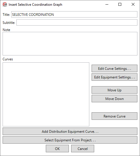
Insert Selective Coordination Graph Dialog Box
-
Title: The title to be used for the graph.
-
Subtitle: A subtitle to be added below the title for the graph.
-
Note: A note that will appear below the graph when it is inserted on the drawing.
-
Curves ☰ A list of the curves to be displayed in the graph.
-
Press this button to edit the selected curve. The OCP Device Settings dialog box will appear.
-
Press this button to open the Panel Edit dialog box for the selected distribution equipment, or the Instance Edit dialog box for the selected branch circuit device.
-
Press this button to move the selected row up in the list of curves.
-
Press this button to move the selected row down in the list of curves.
-
Press this button to remove the selected row from the list of curves.
-
Press this button to add a distribution equipment curve to the list of curves.
If the selected distribution equipment has curves defined for the feeder and main disconnect, you will be prompted to specify which curve to add.

-
Press this button to select a distribution equipment or branch circuit device on the model or on the single-line diagram to add to the list of curves.
The dialog box will close and you will be prompted to specify a device.
Select family instance to edit:The dialog box will reopen with the curve for the selected device added.If you selected a distribution equipment that has curves defined for the feeder and main disconnect, you will be prompted to specify which curve to add.
Inserting the Selective Coordination Graph on the Drafting View
To insert the selective coordination graph on the drafting view, press the button. The settings you specified in the dialog box will be used for the graph you insert.
You will be prompted for the insertion location of the graph.
Specify insertion point of selective coordination graph:
The location you specify will be used as the top-left corner for the graph.
There are several options that affect the default settings and overall appearance of the selective coordination graph. See the Selective Coordination Graph Project Options section for more information.