Ductwork Across Multiple Floors
This tutorial teaches you how to connect ductwork across multiple floors and drawings.
Open drawing M-1.0.
Erase Existing Ductwork
-
Run the
Erase Duct command.
Ribbon:DM HVAC→Ducts→  Erase Duct
Pulldown Menu:DM HVAC→Duct Centerlines→Erase Duct -
Select the vertical duct and first horizontal duct.
The ducts will be erased. This will make it easier to connect to the system later.
Insert AHU & Duct
-
Open drawing M-1.3.
-
Run the
Insert Equipment command. The Insert MEQ dialog box will open.
Ribbon:DM HVAC→MEQ→  Insert Equipment
Pulldown Menu:DM HVAC→Mechanical Equipment→Insert Equipment -
Make the following changes:
- Set Description to AHU.
- Set Width to 60.
- Set Length to 36.
- Set Height to 72.
- Set Elevation to 0-6.
-
Press the button to close the dialog box.
-
Follow the prompts at the command line to insert the equipment over the HVAC chase area on the drawing.
-
Run the
Insert Duct command.
Ribbon:DM HVAC→Ducts→  Insert Duct
Pulldown Menu:DM HVAC→Duct Centerlines→Insert Duct -
Select a point inside the HVAC chase area.
-
Type V at the command line to insert a vertical duct. The Duct Information dialog box will open.
-
Set Starting Elevation to 0-6.
-
Set Ending Elevation to 0.
-
In Sizing Criteria, set Sizing Method ▾ to Static Regain.
-
Press the button to close the dialog box.
-
Press ENTER to end the command.
Insert Drawing to Drawing Connection From M-1.3 to M-1.1
-
Run the
Insert Drawing to Drawing Connection command. The Select drawing to connect to dialog box will open.
Ribbon:DM HVAC→Ducts→  →Insert Drawing to Drawing Connection
Pulldown Menu:DM HVAC→Duct Centerlines→Insert Drawing to Drawing Connection -
Select the M-1.1.dwg file in the folder.
-
Select the duct on the drawing. The Duct Elevation dialog box will open.
-
Set Duct elevation on other drawing to 12-6.
-
Press the button. Drawing M-1.1 will open and you will be prompted to continue inserting ducts.
-
Type V at the command line to insert a vertical duct. The Duct Information dialog box will open.
-
Set Ending Elevation to 0.
-
Press the button to close the dialog box.
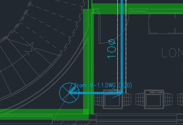
Insert Drawing to Drawing Connection from M-1.1 to M-1.0
-
Run the
Insert Drawing to Drawing Connection command. The Select drawing to connect to dialog box will open.
Ribbon:DM HVAC→Ducts→ →Insert Drawing to Drawing Connection
Pulldown Menu:DM HVAC→Duct Centerlines→Insert Drawing to Drawing Connection -
Select the M-1.0.dwg file in the folder.
-
Select the vertical duct on the drawing. The Duct Elevation dialog box will open.
-
Set Duct elevation on other drawing to 13-6.
-
Press the button. Drawing M-1.0 will open and you will be prompted to continue inserting ducts.
-
Type V at the command line to insert a vertical duct. The Duct Information dialog box will open.
-
Set Ending Elevation to 11.
-
Press the button to close the dialog box.
-
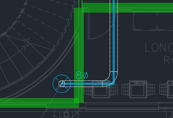
Draw a duct to the duct in the long copy room.
-
Run the
Fillet Ducts command.
Ribbon:DM HVAC→Ducts→  Fillet Ducts
Pulldown Menu:DM HVAC→Duct Centerlines→Fillet Ducts -
Select the duct you just drew, then the duct connected to the rest of the system.
The ductwork and drawing to drawing connections will be connected to the system.
Calculate Airflow & Size Ducts
-
Open drawing M-1.3.
-
Run the
Ductwork Calculations command. The Duct Calculations dialog box will open.
Ribbon:DM HVAC→Ducts→  Ductwork Calculations
Pulldown Menu:DM HVAC→Calculations→Ductwork Calculations -
Set 🔘 Ducts to Use to Ducts in a System.
-
Press the button to select a duct system to calculate.
-
Select a duct on the drawing.
-
Run the
Query Duct command.
Ribbon:DM HVAC→Ducts→  Query Duct
Pulldown Menu:DM HVAC→Duct Centerlines→Query Duct -
Select the vertical duct on the drawing. The Duct Information dialog box will open.
The duct should show airflow and pressure.