Layers
The
Visit the General Customization Commands section for more information about how the
Changes made to layers using this command do not transfer to the drawing automatically.
After making changes, run the Update Drawing Layers to Match Project List command to update the layer definitions on the drawing.
To customize the layers project list, go to
Ribbon: ![]() Layers
Layers
Pulldown Menu:
To customize the layers standards list, go to
Ribbon: ![]() Layers
Layers
Pulldown Menu:
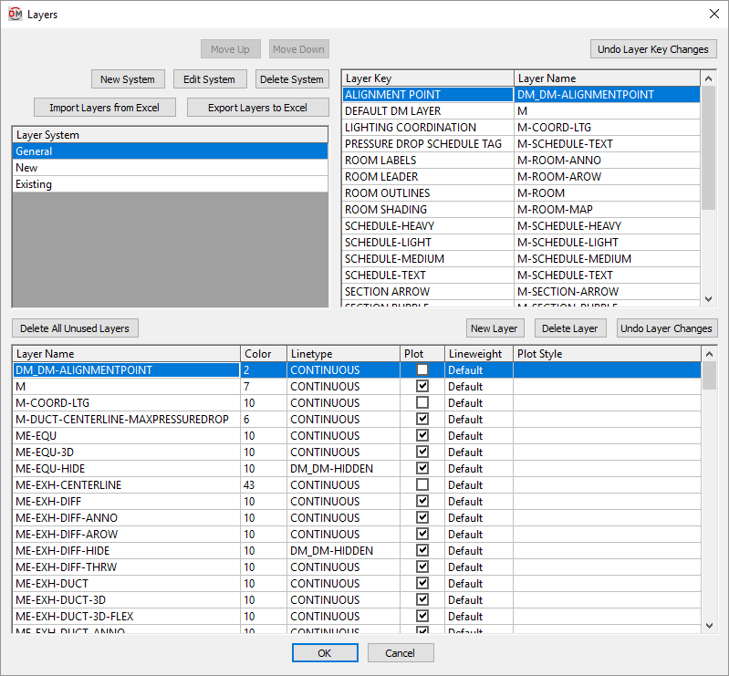
Layers Dialog Box
Layer Systems
-
Press this button to move the selected row up in the Layer System ☰ list.
-
Press this button to move the selected row down in the Layer System ☰ list.
-
Press this button to create a new layer system.
-
Press this button to rename the selected layer system.
-
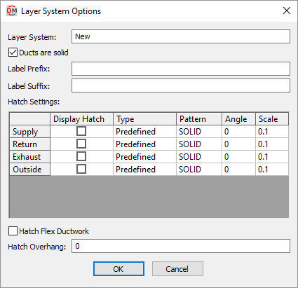
Layer System: The name of the layer system.
-
☐ Ducts are solid Whether ducts on the layer system are drawn with solid lines. If you want ducts on the layer system to be drawn with dashed lines, uncheck this. Visit the How to Make Dashed Ductwork article in the knowledge base for more information.
-
Label Prefix: Text that is added before the label on ductwork in the layer system.
-
Label Suffix: Text that is added after the label on ductwork in the layer system.
Hatch Settings
The following options can be set for different types of duct hatching in the layer system. The hatching that is displayed is based upon the Airflow ▾ setting of the duct.
-
☐ Display Hatch Whether hatching is displayed on the duct.
-
Type ▾ The type of hatching pattern that is displayed.
- Predefined Displays the AutoCAD hatching set in the Pattern ▾ column.
- Custom Displays a custom hatching specified in the Pattern ▾ column.
-
Pattern ▾ The hatching pattern to be displayed.
-
Angle The angle at which the hatching pattern is displayed.
-
Scale The scale of the hatching pattern.
-
☐ Hatch Flex Ductwork Whether hatching is displayed on flex ductwork.
-
Hatch Overhang: How far the hatching extends past the sides of the duct, in inches on the printed page.
-
-
-
Press this button to delete the selected layer system.
-
Layer System ☰ The list of layer systems currently defined.
- General This layer system is used to store all of the layers not associated with devices, such as schedules. Devices cannot be assigned to this layer system. It cannot be deleted or moved.
Layer Keys
-
Press this button to revert the layer key settings to their values when the dialog box was opened.
-
Layer Key ☰ This column lists all of the different items that can be inserted using the software. The names in this column are fixed. Each layer key can be mapped to a layer that will be used when that type of item is inserted on the drawing. Multiple layer keys can use the same layer.
-
Layer Name ▾ This column lists the layer that will be used when inserting items of the corresponding Layer Key ☰ type on the drawing. The layers you can choose from are defined in the lower section of the dialog box.
Layers
The layer list displays all of the layers that can be assigned to layer keys. The settings for each layer can be set in the list.
-
Layer Name The name of the layer.
-
Color The color number of the layer.
-
Linetype The linetype of the layer.
-
☐ Plot Whether the layer will be plotted.
-
Lineweight ▾ The lineweight of the layer. Only used when plotting with STBs.
-
Plot Style The plot style of the layer. Only used when plotting with STBs.
Managing Layers
The following buttons in the Layers dialog box can be used to manage the layers in the dialog box.
-
Press this button to delete all layers that are not associated with a layer key.
-
Press this button to add a new layer.
-
Press this button to delete the selected layer.
-
Press this button to revert the layer settings to their values when the dialog box was opened.
Using Excel to Modify Layer Settings
The and buttons are used to import and export the layer settings to Excel. Using Excel is recommended when modifying large numbers of layer settings.
-
Press this button to load the layer setting information entered in Excel into the dialog box. The layer settings will be applied to the selected layer system.
-
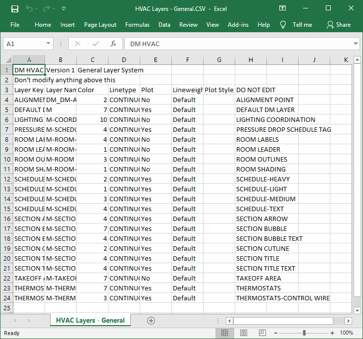
Press this button to export the layer settings to a CSV file that can be opened in Excel. The Save Layer File As dialog box will open.
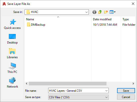
The currently selected layer system will be saved to the file you specify. The file will be opened for immediate editing. When modifying the file, do not change the header rows, the first column, or the last column. Restrict your changes to the Layer Name, Color, Linetype, ☐ Plot, Lineweight ▾, and Plot Style columns.