Options
The
Visit the General Customization Commands section for more information about how the
To edit the options project list, go to
Ribbon: ![]() Options
Options
Pulldown Menu:
To edit the options standards list, go to
Ribbon: ![]() Options
Options
Pulldown Menu:
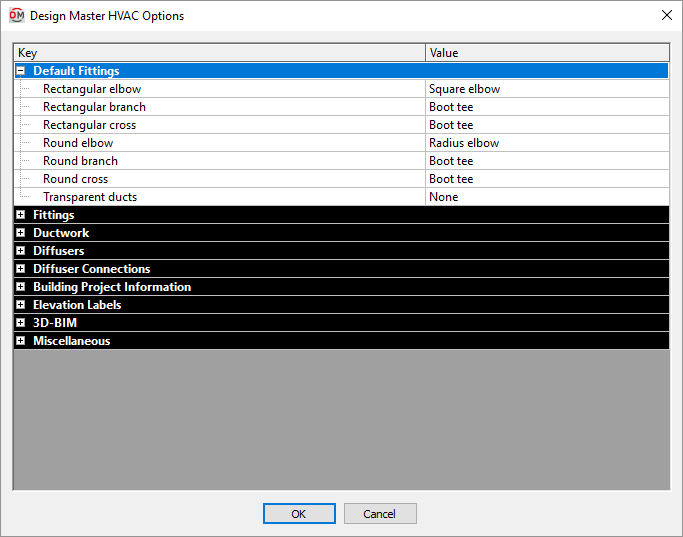
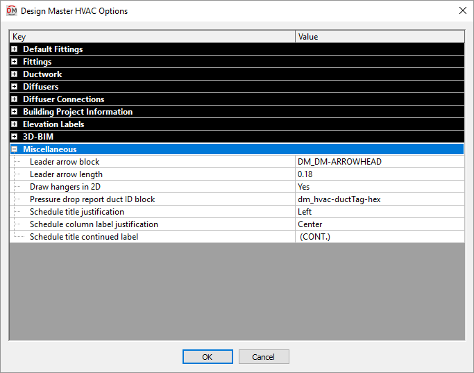
Design Master HVAC Options Dialog Box
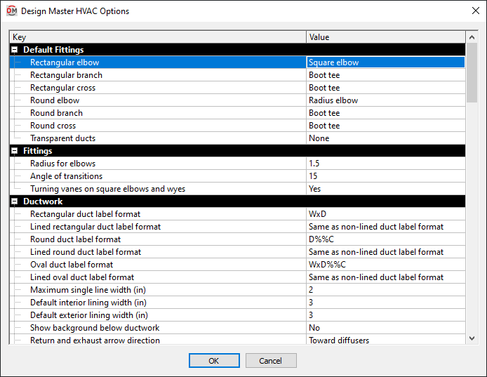
The Design Master HVAC Options dialog box contains a list of all of the options and their current settings. The options are arranged in groups in the list.
Editing a Setting
To edit an option setting, select the Value ☰ in the list and enter a new value.
Press the button to save your changes.
If the change you made to the options does not immediately appear on the drawing, run the Coordinate Drawings and Database command. This command will update the drawing to use the new settings you have specified.
Default Fittings
-
Rectangular elbow ▾ The default fitting used for elbows in rectangular ducts.
- Square elbow A Square Elbow fitting is used. Visit Turning Vanes on Square Elbows and Wyes ▾ in the Fittings options section for whether the elbow includes turning vanes.
- Radius elbow A Radius Elbow fitting is used. Visit Radius for Elbows in the Fittings options section for the radius used for the elbows.
-
Rectangular branch ▾ The default fitting used for a single takeoff in a rectangular duct.
- Any angle tee A Variable Angle Branch fitting is used.
- Boot tee A Boot Tee fitting is used.
- Conical tee A Conical Tee fitting is used.
- Straight takeoff A Straight Tee fitting is used.
- Wye A Wye / Bullnose Tee fitting is used.
- Transition tee A Transition Tee fitting is used.
-
Rectangular cross ▾ The default fitting used for a cross in a rectangular duct.
- Boot tee A Boot Tee fitting is used.
- Conical tee A Conical Tee fitting is used.
- Straight takeoff A Straight Tee fitting is used.
- Transition tee A Transition Tee fitting is used.
-
Round elbow ▾ The default fitting used for elbows in round and flat oval ducts.
- Square elbow A Square Elbow fitting is used. Visit Turning Vanes on Square Elbows and Wyes ▾ in the Fittings options section for whether the elbow includes turning vanes.
- Radius elbow A Radius Elbow fitting is used. Visit Radius for Elbows in the Fittings options section for the radius used for the elbows.
-
Round branch ▾ The default fitting used for a single takeoff in a round or flat oval duct.
- Any angle tee A Variable Angle Branch fitting is used.
- Boot tee A Boot Tee fitting is used.
- Conical tee A Conical Tee fitting is used.
- Straight takeoff A Straight Tee fitting is used.
- Wye A Wye / Bullnose Tee fitting is used.
- Transition tee A Transition Tee fitting is used.
-
Round cross ▾ The default fitting used for a cross in a round or flat oval duct.
- Boot tee A Boot Tee fitting is used.
- Conical tee A Conical Tee fitting is used.
- Straight takeoff A Straight Tee fitting is used.
- Transition tee A Transition Tee fitting is used.
-
Transparent Ducts ▾ The fitting inserted in the previous duct before a transparent duct. Visit the Previous and Next Ducts section for information about determining which duct is the previous duct.
- End Cap An End Cap fitting is inserted at the end of the previous duct.
- None No fitting is inserted at the end of the previous duct.
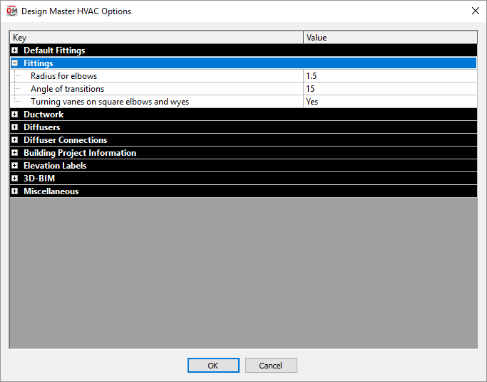
Fittings
-
Radius for elbows The default radius of radius elbow fittings. The radius can be set for individual fittings by manually inserting the fitting using the Radius Elbow command.
-
Angle of transitions The angle of duct transitions.
-
Turning vanes on square elbows and wyes ▾ Whether square elbows and wyes include turning vanes by default. Turning vanes can be toggled for individual fittings by manually inserting the fitting using the Square Elbow or Wye / Bullnose Tee commands.
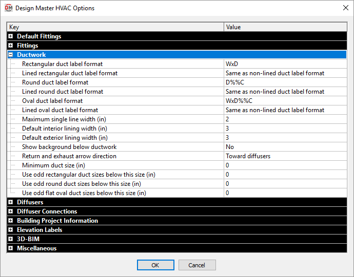
Ductwork
-
Rectangular duct label format The duct label used on rectangular ducts. Visit the Duct Label Format Codes section below for more information about the values that can be automatically inserted in the label.
-
Lined rectangular duct label format The duct label used on lined rectangular ducts. Visit the Duct Label Format Codes section below for more information about the values that can be automatically inserted in the label.
- Same as non-lined duct label format The duct label for lined rectangular ducts will use the Rectangular duct label format option.
-
Round duct label format The duct label used on round ducts. Visit the Duct Label Format Codes section below for more information about the values that can be automatically inserted in the label.
-
Lined round duct label format The duct label used on lined round ducts. Visit the Duct Label Format Codes section below for more information about the values that can be automatically inserted in the label.
- Same as non-lined duct label format The duct label for lined round ducts will use the Round duct label format option.
-
Oval duct label format The duct label used on flat oval ducts. Visit the Duct Label Format Codes section below for more information about the values that can be automatically inserted in the label.
-
Lined oval duct label format The duct label used on lined flat oval ducts. Visit the Duct Label Format Codes section below for more information about the values that can be automatically inserted in the label.
- Same as non-lined duct label format The duct label for lined flat oval ducts will use the Oval duct label format option.
-
Maximum single line width (in) The maximum width that ducts with their Graphics ▾ set to Automatic will be drawn single-line. All ducts larger than this value will be drawn with double-line.
-
Default interior lining width (in) The default Interior Lining Width when creating or modifying ducts.
-
Default exterior lining width (in) The default Exterior Lining Width when creating or modifying ducts.
-
Show background below ductwork ▾ Whether the background and other entities below ductwork are visible.
- Yes The background and other entities are visible. The ductwork entities are inserted significantly below their proper elevation. The ducts will hide each other but nothing else on the drawing.
- No The background and other entities are not visible. The ductwork entities are inserted at their proper elevation. Anything below that elevation will be hidden.
-
Return and exhaust arrow direction ▾ The direction that centerline arrows point for return and exhaust ductwork.
- Toward diffusers Arrowheads point toward diffusers. The centerlines point in the opposite direction from the flow of the duct. Determining the next and previous duct is the same as with supply ducts.
- Flow direction Arrowheads point in the direction of flow, away from diffusers. Determining the next and previous duct depends upon the type of duct.
-
Minimum duct size (in) The minimum size to which ducts will be resized.
-
Use odd rectangular duct sizes below this size (in) By default, ducts are resized to even sizes. Rectangular ducts resized below this value will be sized to even or odd sizes.
-
Use odd round duct sizes below this size (in) By default, ducts are resized to even sizes. Round ducts resized below this value will be sized to even or odd sizes.
-
Use odd flat oval duct sizes below this size (in) By default, ducts are resized to even sizes. Flat oval ducts resized below this value will be sized to even or odd sizes.
Duct Label Format Codes
The Duct Label Format options use special codes to insert duct dimensions in the duct label. These codes are replaced with dimension values from the database when the labels are shown on the drawing.
Multiple codes can be included in a duct label, allowing you to label both interior and exterior dimensions, or provide the dimension in both imperial and metric units.
Interior dimensions are the specified width and depth for the duct.
Exterior dimensions are the interior dimensions plus two times the interior lining (once for the lining on each side of the duct). Exterior dimensions do not include exterior lining width.
Standard / Imperial Dimensions: Duct dimensions in inches.
- W Interior width in inches.
- D Interior depth or diameter in inches.
- WE Exterior width in inches.
- DE Exterior depth in inches.
Centimeter Dimensions: Duct dimensions converted from inches to centimeters.
- WM Interior width in centimeters.
- DM Interior depth or diameter in centimeters.
- WME Exterior width in centimeters.
- DME Exterior depth in centimeters.
Millimeter Dimensions: Duct dimensions converted from inches to millimeters.
- WMM Interior width in millimeters.
- DMM Interior depth or diameter in millimeters.
- WMME Exterior width in millimeters.
- DMME Exterior depth in millimeters.
Soft Millimeter Dimensions: Duct dimensions converted from inches to millimeters using 25 millimeters per inch (rather than 25.4 millimeters per inch).
- WMMS Interior width in soft millimeters.
- DMMS Interior depth or diameter in soft millimeters.
- WMMSE Exterior width in soft millimeters.
- DMMSE Exterior depth in soft millimeters.
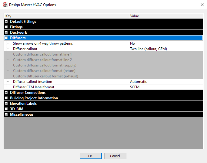
Diffusers
-
Show arrows on 4 way throw patterns ▾ Whether throw arrows are shown on diffusers when they are first inserted on the drawing. Once a diffuser is inserted on the drawing, use the Insert Throw Arrow and Remove Throw Arrow commands to modify the throw arrows that are displayed. Changing this option will not affect throw arrows on diffusers already on the drawing.
-
Diffuser callout ▾ The format of diffuser callouts.
- Single line (callout-CFM) A single line listing the diffuser callout and the airflow.
- Two line (callout, CFM) Two lines of text separated by a line listing the callout on the first line and the airflow on the second.
- Two line (callout, CFM, neck size) Two lines of text separated by a line listing the callout on the first line and the airflow and neck size on the second.
- Three line box A box with three lines of text listing the callout on the first line, the neck size on the second, and the airflow on the third.
- Three line box (rounded) A box with round corners with three lines of text listing the callout on the first line, the neck size on the second, and the airflow on the third.
- Circle A circle with two lines of text listing the callout on the first line and the airflow on the second.
- Square with neck dimension A box with a single line listing the neck size, the callout, and the airflow.
- Hexagon A hexagon with two lines of text listing the callout on the first line and the airflow on the second.
- Triangle A triangle with the callout listed inside it and the airflow listed below.
- CFM only The airflow is listed. No callout or neck size is displayed.
- Show neck, face, and throw Two lines of text separated by a line listing the neck size, face size, and callout on the first line and the airflow and throw pattern on the second.
- Dome A dome with two lines of text listing the callout on the first line and the airflow on the second.
- Flow arrow underline Two lines of text separated by a line listing the callout on the first line and the airflow on the second. The line between the two lines of text connects to the leader and points in the direction of the airflow into or out of the diffuser.
- Custom block The callout is inserted using a custom block. Visit the Creating a Custom Diffuser Callout Block article in the knowledge base for more information about how to create a custom block.
- Custom single line A single line of with custom text. The text is set using the Custom diffuser callout format options below.
- Custom two line Two lines of text separated by a line. The text in the two lines is set using the Custom diffuser callout form line 1 and Custom diffuser callout form line 2 options below.
-
Custom diffuser callout format line 1 The format used for the top line of the diffuser callout when the Diffuser callout ▾ option is set to Custom two line. Visit the Custom Diffuser Callout Codes section below for more information about the values that can be automatically inserted in the label.
-
Custom diffuser callout format line 2 The format used for the bottom line of the diffuser callout when the Diffuser callout ▾ option is set to Custom two line. Visit the Custom Diffuser Callout Codes section below for more information about the values that can be automatically inserted in the label.
-
Custom diffuser callout format (supply) The format used for supply diffuser callouts when the Diffuser callout ▾ option is set to Custom single line. Visit the Custom Diffuser Callout Codes section below for more information about the values that can be automatically inserted in the label.
-
Custom diffuser callout format (return) The format used for return diffuser callouts when the Diffuser callout ▾ option is set to Custom single line. Visit the Custom Diffuser Callout Codes section below for more information about the values that can be automatically inserted in the label.
- Same as supply Return diffuser callouts will use the Custom diffuser callout format (Supply) option value.
-
Custom diffuser callout format (exhaust) The format used for exhaust diffuser callouts when the Diffuser callout ▾ option is set to Custom single line. Visit the Custom Diffuser Callout Codes section below for more information about the values that can be automatically inserted in the label.
- Same as supply Exhaust diffuser callouts will use the Custom diffuser callout format (Supply) option value.
-
Diffuser callout insertion ▾ How diffuser callouts are inserted when a new diffuser is inserted on the drawing. Once the diffuser and diffuser callout are inserted on the drawing, use the Insert or Move Callout and Remove Callout commands to modify the callouts. Changing this option will not affect diffusers and diffuser callouts already on the drawing.
- Automatic The diffuser callout is automatically inserted to the right of the diffuser.
- Manual You are prompted to specify the location of the diffuser callout after the diffuser is inserted.
- Not inserted Diffusers are inserted without diffuser callouts.
-
Diffuser CFM label format How the airflow value for a diffuser is displayed in the callout. $CFM will be replaced with the actual CFM value of the diffuser. $LPS will be replaced with the airflow in liters per second. Other text will be displayed exactly as it is entered.
The default value for this option is $CFM, which displays only the CFM value for the diffuser.
The most common change to this option is to set it to $CFM CFM, which displays the CFM value with a "CFM" label.
Another common change is to include the $LPS code to display the airflow in metric units.
Custom Diffuser Callout Codes
The Custom diffuser callout options use special codes to insert information about the diffuser in the callout text. These codes are replaced with values from the database when the callout is shown on the drawing.
- $CALLOUT The diffuser callout.
- $CFM The diffuser airflow. The format for the replacement string is based upon the Diffuser CFM Label format option.
- $NECK The neck size of the diffuser.
- $FACE The face size of the diffuser.
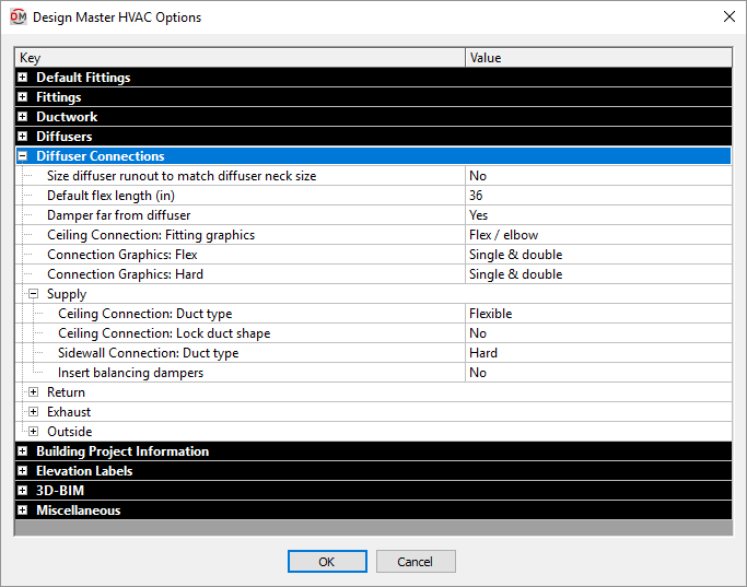
Diffuser Connections
-
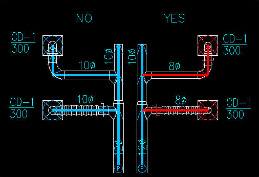
Size diffuser runout to match diffuser neck size ▾ Whether the runout to a diffuser is sized to match the diffuser neck size or based upon the airflow in the duct. The runout is defined as all of the ducts from the diffuser to the first branch.
- Yes The runouts ignore the sizing criteria and are sized to match the diffuser neck size.
- No The runouts are sized using the sizing criteria like the other ducts in the system.
In the example below, the ducts on the left side have been sized with this option set to No. The ducts on the right side have been sized with this option set to Yes. The ducts in red have been sized to match the neck size of the connected diffusers.
-
Default flex length (in) The maximum length of flex duct inserted during diffuser connection commands. If the diffuser connection length exceeds this distance, hard duct is inserted to make up the rest of the distance.
Once the diffuser connection is inserted, this value is no longer used. Changing this value will not change the length of flex duct of diffuser connections that were previously inserted. Moving the diffuser or modifying the duct layout can result in situations where the flex length exceeds this value.
-
Damper far from diffuser ▾ Where balancing dampers are inserted in the duct system.
- Yes Balancing dampers are inserted as far from the diffuser as possible. They will be inserted at the start of the duct that begins the branch leading to the diffuser.
- No Balancing dampers are inserted as close to the diffuser as possible. If there is flex duct leading to the diffuser, the balancing damper will be inserted just before the flex duct. Otherwise, they will be inserted just before the diffuser.
-
Ceiling Connection: Fitting graphics ▾ The graphics used when drawing ceiling diffuser connections in 2D.
- Flex / Elbow For connected flex ducts, flex duct is drawn connecting to the diffuser. For connected hard ducts, an elbow is drawn connecting to the diffuser.
- Elbow An elbow is drawn connecting to the diffuser.
- Tee An vertical tee is drawn connecting to the diffuser.
-
Connection Graphics: Flex ▾ The graphics used when drawing flexible connections to ductwork in 2D.
- Single The flex ductwork is drawn single-line, regardless of the size of the flex duct. The ducts in the diffuser connection are inserted with their Graphics ▾ field set to Single.
- Double The flex ductwork is drawn double-line, regardless of the size of the flex duct. The ducts in the diffuser connection are inserted with their Graphics ▾ field set to Double.
- Single & double The flex ductwork is drawn single-line and double-line, depending upon the width of the flex duct and the Maximum single line width option in the Ductwork options section. The ducts in the diffuser connection are inserted with their Graphics ▾ field set to Automatic.
-
Connection Graphics: Hard ▾ The graphics used when drawing hard connections to ductwork in 2D.
- Single The ductwork is drawn single-line, regardless of the size of the duct. The ducts in the diffuser connection are inserted with their Graphics ▾ field set to Single.
- Double The ductwork is drawn double-line, regardless of the size of the duct. The ducts in the diffuser connection are inserted with their Graphics ▾ field set to Double.
- Single & double The ductwork is drawn single-line and double-line, depending upon the width of the duct and the Maximum single line width option in the Ductwork options section. The ducts in the diffuser connection are inserted with their Graphics ▾ field set to Automatic.
Supply, Return, Exhaust, Outside
These options set the defaults for each section in the Change Connection Type command.
-
Ceiling Connection: Duct type ▾ The material type used for the duct when connecting to a floor or ceiling diffuser.
- Flexible Flexible ducts are used to connect to the diffuser. The length of flexible duct is limited by the Default flex length option. If the connection is longer than that length, hard duct is used for part of the connection.
- Hard Hard ducts are used to connect to the diffuser.
-
Ceiling Connection: Lock duct shape ▾ Whether ducts that are inserted as part of the diffuser connection have their shapes locked.
- No The duct shapes are not locked. The duct shape will be set when the duct is sized.
- Round The duct shapes are locked as round.
- Rectangular The duct shapes are locked as rectangular.
- Flat oval The duct shapes are locked as flat oval.
-
Sidewall Connection: Duct type ▾ The material type used for the duct when connecting to a sidewall diffuser.
- Flexible Flexible ducts are used to connect to the diffuser. The length of flexible duct is limited by the Default flex length option. If the connection is longer than that length, hard duct is used for part of the connection.
- Hard Hard ducts are used to connect to the diffuser.
-
Insert balancing dampers ▾ Whether a balancing damper is inserted in the duct connected to the diffuser.
Building Project Information
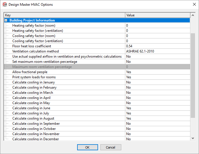
All of these options set the default values that appear in the Project Info command. These values can be changed in the Project Information dialog box. These options are provided so that you can specify the values in the standards database. The values in the standards database will be used as the default values on new projects.
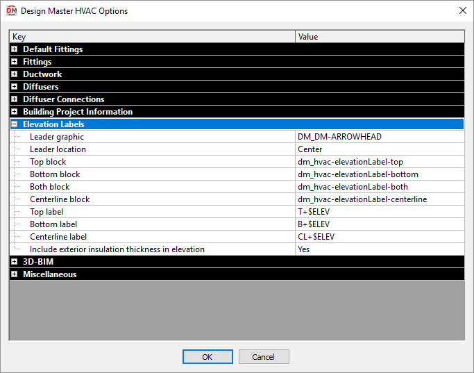
Elevation Labels
-
Leader graphic The block used for elevation label leaders. You can set the block by typing a new name or selecting Browse. . . and selecting the new name.
-
Leader location Where the leader points on the duct.
- Edge The leader points to the edge of the duct.
- Center The leader points to the center of the duct.
- Edge The leader points to the edge of the duct.
-
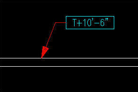
Top block The block used for the elevation label when the Insert Top Elevation Label command is used.
-
Bottom block The block used for the elevation label when the Insert Bottom Elevation Label command is used.
-
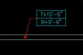
Both block The block used for the elevation label when the Insert Top and Bottom Elevation Label command is used.
-
Centerline block The block used for the elevation label when the Insert Centerline Elevation Label command is used.
-
Top label The text that is used to display the top elevation in the label. $ELEV is replaced with the elevation.
-
Bottom label The text that is used to display the top elevation in the label. $ELEV is replaced with the elevation.
-
Centerline label The text that is used to display the top elevation in the label. $ELEV is replaced with the elevation.
-
Include exterior insulation thickness in elevation ▾ Whether the top and bottom elevations include the exterior insulation thickness.
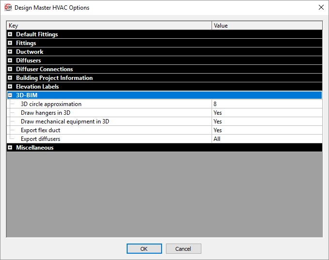
3D-BIM
-
3D circle approximation Circles are approximated in the 3D model as polygons. This option sets the number of sides of a polygon used to represent a circle. Higher numbers more closely approximate a circle, but greatly increase file size. The minimum number value for this option is 8.
-
Draw hangers in 3D ▾ Whether hangers are drawn in 3D. This setting has no impact on the 3D-BIM export commands. It only affects whether they are visible in AutoCAD.
-
Draw mechanical equipment in 3D ▾ Whether mechanical equipment is drawn in 3D. This setting has no impact on the 3D-BIM export commands. It only affects whether they are visible in AutoCAD.
-
Export flex duct ▾ Whether flex ducts are exported.
-
Export diffusers ▾ Which diffusers are exported.
- All All diffusers will be exported.
- Ceiling only Only ceiling diffusers will be exported.
- Sidewall only Only sidewall diffusers will be exported.
- Connected to hard ducts Only diffusers connected using hard ducts will be exported. Visit the Change Connection Type section for more information.
- None No diffusers will be exported.
Miscellaneous
-
Leader arrow block The block used for leader arrowheads.
-
Leader arrow length The length of the leader arrowhead.
-
Draw hangers in 2D ▾ Whether hangers are drawn in 2D.
-
Pressure drop report duct ID block The block used to label ducts in the pressure drop report and on the drawing. Visit the Insert Pressure Drop Report section for more information.
-
Schedule title justification ▾ The justification for the title at the top of all of the schedules.
- Left The schedule title is justified to the left.
- Center The schedule title is centered.
-
Schedule column label justification ▾ The justification for the label at the top of each column in all of the schedules.
- Left The column labels are justified to the left.
- Center The column labels are centered.
-
Schedule title continued label The text in this option is added to the schedule title when the schedule is broken into multiple sections.
When inserting schedules, there is an option to set a maximum height for the schedule. If the schedule exceeds this height, the schedule is continued in a second section next to the first. The title of the second and following sections is the schedule title plus the text in the Schedule title continued label option.