Insert Diffuser
To insert a diffuser on a drawing, go to
Ribbon: ![]() Insert Diffuser
Insert Diffuser
Pulldown Menu:
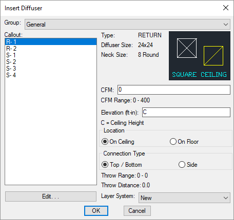
Insert Diffuser Dialog Box
-
Group: ▾ The active diffuser group. Visit the Common Groups Dialog Box Features section for more information.
-
Callout: ☰ The type of diffuser to be inserted. The list of diffusers available is defined in the Diffuser Project Schedule command.
The selected callout controls the set values displayed in the dialog box, such as CFM Range. Visit the Common Diffuser Information section for more information about these values. To change these values, you must change the definition of the diffuser type in the project schedule.
-
Press this button to open the Diffuser Project Schedule with the selected diffuser active.
-
CFM: The airflow through the diffuser.
-
Elevation: The elevation of the diffuser. Visit the Elevation section for more information.
Enter C to indicate the elevation is the same as the ceiling height of the room in which the diffuser is inserted. You must have rooms inserted on the drawing to use this value. Visit the Create Room section for more information.
-
🔘 Location Where the diffuser is located. This setting controls whether ductwork connects to the diffuser from above or below.
- On Ceiling The diffuser is located in the ceiling. The ductwork connecting to the diffuser comes from above.
- On Floor The diffuser is located on the floor. The ductwork connecting to the diffuser comes from below.
-
🔘 Connection Type How ducts connect to the diffuser.
- Top / Bottom Ducts connect to the top or bottom of the diffuser, depending upon whether it is located on the ceiling or the floor.
- Side Ducts connect to the side of the diffuser.
-
Layer System: ▾ Visit the Layer System section for more information.
Inserting the Diffuser on the Drawing
To insert a diffuser on the drawing, press the button. The settings specified in the dialog box will be used for the inserted diffuser. You will be prompted to identify where on the drawing the diffuser is to be inserted.
Specify insertion point or [Corner/Middle]:
-
Specify insertion pointSpecify the location on the drawing where the diffuser is to be inserted. -
CornerType C to change the insertion point of the diffuser to a corner on the diffuser block. Type C again to select a different corner. This option is only available for rectangular diffusers. -
MiddleType M to change the insertion point of the diffuser to the middle of the diffuser block. This option is only available for rectangular diffusers.
You then will be prompted for the rotation angle.
Specify rotation:
You will then be prompted to insert another diffuser of the same type. Continue to insert diffusers, or press ENTER to finish the command.
You can customize diffuser callouts and whether throw arrows are shown when diffusers are inserted on the drawing. Visit the Diffusers Options section for more information.