Insert Drawing to Drawing Connection
The
A drawing-to-drawing connection duct is inserted as a duct centerline on the two drawings that are being connected. Both centerlines refer to the same duct in the database.
A label is inserted with the centerline. The end of the centerline that does not have a label is where the duct starts or ends on the current drawing. The location of the end without the label is used to establish connections to other ducts on the drawing. The end of the centerline with the label is for display purposes only. The specific location of this end is not used for calculation purposes. The label lists the other drawing that the duct connects to and the duct ID number.
The duct ID is the number used to represent the duct in the database. The duct ID will match on the two drawings and can be used to verify that you are viewing the same drawing-to-drawing connection on both drawings. The specific value is automatically generated by the database and cannot be changed.
To insert a drawing-to-drawing connection duct, go to
Ribbon: ![]() →Insert Drawing to Drawing Connection
→Insert Drawing to Drawing Connection
Pulldown Menu:
The drawing-to-drawing connection will start on the drawing that is currently active. The active drawing should be the drawing where the duct is closer to the fan.
You will be prompted to select the drawing to which the duct will connect. The selected drawing should be closer to the diffusers.
Select drawing to connect to Dialog Box
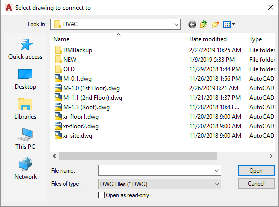
You will then be prompted to select the duct that is to be connected to another drawing.
Select duct or label to connect to another drawing:
The Duct Elevation dialog box will open.

- Duct elevation on other drawing: The elevation of the duct on the other drawing. This elevation will be relative to the elevation of the alignment point on the other drawing. If the drawing-to-drawing connection duct is going up, set this value to 0. If the drawing-to-drawing connection duct is going down, set this value to the wall height on the floor below.
Press the button to insert the drawing-to-drawing connection.
The drawing you are connecting to will open. If the other drawing cannot be opened automatically, you will be prompted to open it manually. Once the drawing is open, the command will continue.
If there are multiple alignment point areas on the drawing, you will be prompted to specify the area in which to insert the duct.
Specify point in alignment point area to use:
The drawing-to-drawing connection will be inserted on the drawing, either in the selected alignment point area or in the only area on the drawing. The insertion location will be in the same location relative to the alignment point as on the first drawing.
You will then be prompted to insert additional ducts connected to the new drawing-to-drawing connection duct. Visit the Insert Duct section for more information about inserting the additional ducts.