Performing Selective Coordination
How to perform selective coordination.
Start in the SELECTIVE COORDINATION drafting view.
Set Breaker Curves for Transformer T1 and Panel L
-
Run the
ElectroBIM Design→ command. If prompted to select a distribution equipment to edit, press ESC. The Panel Edit dialog box will open. Panel Edit
 -
Select transformer T1 from the list.
-
Beside OCP Trip ▾, press the button. The OCP Device Settings dialog box will open.
-
Make the following changes:
- Set Manufacturer ☰ to GE.
- Set Group ☰ to Insulated Case Circuit Breaker > Type SH > MicroVersaTrip PM > 800A Frame.
-
Press the button to close the dialog box.
-
Select panel L from the list and, beside OCP Trip ▾, press the button. The OCP Device Settings dialog box will open.
-
Make the following changes:
- Set Manufacturer ☰ to Square D.
- Set Group ▾ to Low Voltage Power Circuit Breakers > MasterPact NW > MicroLogic 2.0.
-
Press the button to close the dialog box.
-
Press the button to close the dialog box.
Create the Selective Coordination Graph
-
Run the
ElectroBIM Design→ command. The Insert Selective Coordination Graph dialog box will open. Graph Insert
 -
Press the button. The Select Distribution Equipment dialog box will open.
-
Select transformer T1 from the list and press the button to close the dialog box.
-
Repeat steps 2-3 for panel L.
-
Press the button to close the dialog box.
-
Follow the prompts to insert the graph on the drafting view.
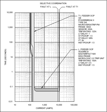
Modify the Breaker Curve
-
Run the
ElectroBIM Design→ command. Curve Edit
 -
On the graph, select the curve or label for transformer T1.The OCP Device Settings dialog box will open.
-
Make the following changes:
- Set Short-time Pickup ☰ to 2.
- Set I² T ☰ to Out.
- Set Instantaneous Pickup ☰ to 2.
-
Press the button to close the dialog box.
The graph will update to reflect the changes.
