Inserting Panels and Transformers on a Drawing
This tutorial teaches you how to insert panels and transformers on a drawing. You will insert them on both your lighting and your power drawings. Open drawing E-1.1.
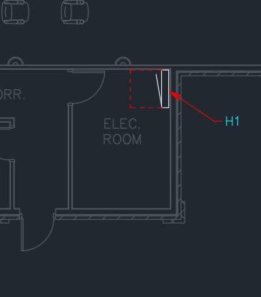
Insert Panel H1
-
Run the
Insert Plan View Block command. The Insert Distribution Equipment Block dialog box will open.
Ribbon:DM Electrical→Distribution Equipment→  Insert Plan View Block
Pulldown Menu:DM Electrical→Distribution Equipment→Insert Plan View Block -
Select H1.
-
Set Plan View Block ▾ to 8" x 42" Panel. This setting controls the graphic that is used when the plan view block is inserted.
noteIt can also be set in the
 Panels
 -
Press the button.
-
Follow the prompts at the command line to place the panel in the electrical room.
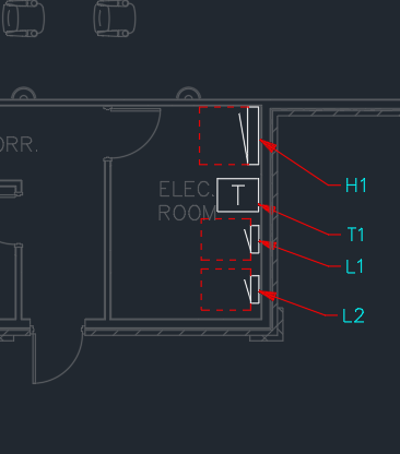
Insert Transformer T1
-
Run the
Insert Plan View Block command. The Insert Distribution Equipment Block dialog box will open.
Ribbon:DM Electrical→Distribution Equipment→ Insert Plan View Block
Pulldown Menu:DM Electrical→Distribution Equipment→Insert Plan View Block -
Select T1.
-
Press the button.
-
Follow the prompts at the command line to place the transformer in the electrical room next to H1.
Insert Panel L1
-
Run the
Insert Plan View Block command. The Insert Distribution Equipment Block dialog box will open.
Ribbon:DM Electrical→Distribution Equipment→ Insert Plan View Block
Pulldown Menu:DM Electrical→Distribution Equipment→Insert Plan View Block -
Select L1.
-
Set Plan View Block ▾ to 6" x 20" Panel.
-
Set Distance to Left to 5.
-
Set Distance to Right to 5.
-
Press the button.
-
Follow the prompts at the command line to place the panel in the electrical room next to T1.
Insert Panel L2
-
Run the
Insert Plan View Block command. The Insert Distribution Equipment Block dialog box will open.
Ribbon:DM Electrical→Distribution Equipment→ Insert Plan View Block
Pulldown Menu:DM Electrical→Distribution Equipment→Insert Plan View Block -
Select L2.
-
Set Plan View Block ▾ to 6" x 20" Panel.
-
Set Distance to Left to 5.
-
Set Distance to Right to 5.
-
Press the button.
-
Follow the prompts at the command line to place the panel in the electrical room next to L1.
Insert the Panels and Transformer on the Power Drawing
-
Open drawing E-2.1,2.
-
Run the
Insert Plan View Blocks in Another Area of Drawing command. The Insert Distribution Equipment Blocks in Another Area or Drawing dialog box will appear.
Ribbon:DM Electrical→Distribution Equipment→  Insert Plan View Blocks in Another Area or Drawing
Pulldown Menu:DM Electrical→Distribution Equipment→Insert Plan View Blocks in Another Area or Drawing -
Select H1, L1, L2, and T1. You can select multiple items in the list using the SHIFT or CTRL key.

-
Press the button.
-
Select a point in the lower alignment point area corresponding to the first floor.
noteYou will be prompted to do this whenever there are two or more alignment point areas on the drawing.
The panels and transformer will be inserted in the same location on drawing E-2.1,2 as they were inserted on drawing E-1.1.
If the panels and transformer are not in the same location, check that the alignment points are inserted in the same location on each drawing.
Move a Panel on Both Drawings
Using the standard CAD MOVE and ROTATE commands, move panel L2 so that it is located on the lower wall in the electrical room.
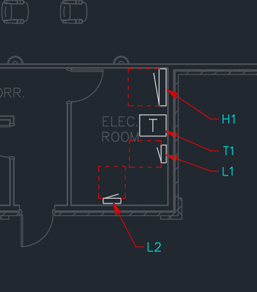
Go back to drawing E-1.1 and run any Design Master command. Panel L2 will move to the new location.