When creating a block from entities, you will be prompted to select entities in the current drawing for use as the block. The entities will be removed from the drawing. A new drawing file containing them will be created
Begin by drawing a picture of the block as it will appear in plan view. Unless you specifically desire certain layers for your block, it is not important which layer is used. The command will convert it the entities to layer zero unless directed otherwise.
To begin the block creation process, select:
DM Plumbing![]() Customization
Customization![]() Block Creation
Block Creation![]() Create Pipe Symbol Block from Entities
Create Pipe Symbol Block from Entities
The Create Pipe Symbol Block dialog box will appear.
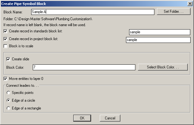
Block Name: the name of the block you are creating. Use a standard naming convention to make finding your blocks easier in the future. All of the default blocks start with dm_plumb-.
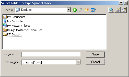
Set Folder: this button allows you to select a folder to save the block into. If you press this button the Select Folder for Pipe Symbol Block dialog box will appear and allow you to choose a folder.
Folder: the folder that the block will be saved to.
Create record in standards block list: check this box if you want to create a record of the block in your standards database and then type the name. The block record will automatically be created. See the Pipe Symbol Blocks > Edit Standards List section for more information about editing this list.
Create record in project block list: check this box if you want to create a record of the block in your project database and then type the name. The block record will automatically be created. See the Pipe Symbol Blocks > Edit Project List section for more information about editing this list.
Block is to scale: check this box if the block is to scale. A block that is to scale will insert on the drawing at the exact dimensions it was created, while a block that is not to scale will change sizes relative to the dimscale setting.
Create Slide: check this box if you wish to create a slide of the block. The slide is only used to identify the block while working within Design Master Plumbing.
Block Color: enter the color number for the slide here.
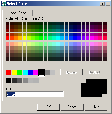
Select Block Color: displays the Select Color dialog box and allows you to choose the color for your slide.
Move entities to layer 0: moves all the entities to layer 0. If you are unsure what to do, check this box.
Connect leaders to: this section allows you to choose how to connect leaders to your blocks. The three options are listed below.
Specify points: allows you to pick specific points on the block to connect to the leaders.
Edge of a circle: has leaders connect to the edge of a circle in the block.
Edge of a rectangle: has leaders connect to the edge of a rectangle in the block.
Once you press OK, the program will prompt you to Select entities to use in the block:
Select any entities you want to include in the block and press ENTER.
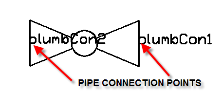
You will then Specify locations pipes will connect to pipe symbol:
Select the points on the block where the pipe it is inserted on will connect to the block.
Then Specify locations leaders will connect to block:
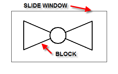
The program will then prompt you to insert the block and make a slide.
Insert the block and then draw a window around it to create the slide.