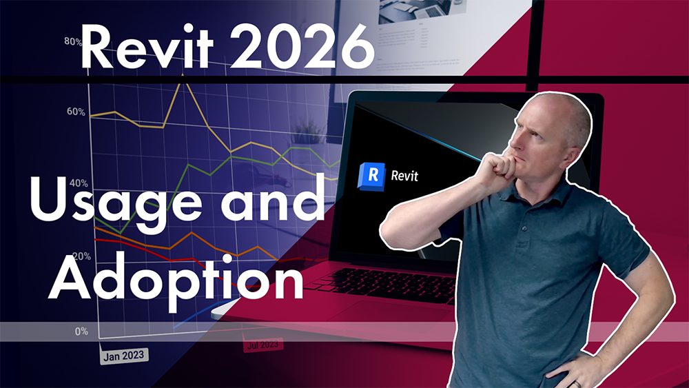
|
You are here: Home > Blog
|
|
July 29th, 2010
If you're new here, you may want to subscribe to my RSS feed. Thanks for visiting! Continuing my series of comparisons between Design Master and Revit MEP, let’s compare how you calculate HVAC heating and cooling load values when your architect sends you 2D drawings.
There are a lot of projects that only have 2D drawings. Most architects are not using Revit (though Autodesk would like you to believe otherwise). Any remodel you do, which is very common in the current economic climate, will at best have a set of 2D DWG files, and might only have a scanned copy of a paper plan. If you cannot handle projects that have 2D plans, you are severely limiting the type of work you can do.
On the Autodesk forums, a Revit user who asks how to handle this situation. The answer he is given is, “I wouldn’t bother using Revit with a 2D drawing.” If all you have are 2D drawings, you can’t use Revit MEP.
In Design Master HVAC, this is not a problem. You do have to manually trace the rooms and specify exterior walls in AutoCAD with our software, but it’s pretty easy. It is the first topic that is covered in our training tutorial.
Even if you decide that Revit MEP is the future and the right product for you, what are you going to do for all the projects where the architect is not using Revit? One option is to limit yourself to new construction with architects using Revit, but that’s a pretty small market you will be chasing. Another is to get Revit MEP for the times when you can use it, but also have another system in place for the rest of your projects.
Or, you could get Design Master HVAC, which works no matter what the architect gives you. You don’t have to limit yourself to only Revit projects, and you do not have to spend your limited time and money learning and maintain two different systems. To learn more about Design Master HVAC, contact us for a free demonstration and 30-day trial.
Posted in General | No Comments »
June 25th, 2010
Continuing my series of comparisons between Design Master and Revit MEP, let’s compare system requirements.
This post describes what one user recommends for using Revit. He is most likely talking about Revit Architecture, but Revit MEP is going to have the same basic requirements:
OS = 64bit Mandatory
RAM = 16 GB Recommended; 8 GB Bare Minimum
Processors = Dual 6 Core Xeon Get the job done fast…-OK Dual Quad Xeons are OK too…
Video Card = 1TB, If it’s on the list below
That is a serious set of computers requirements. The requirements for Design Master are much more modest. You need to be able to run AutoCAD 2004 or later, and that’s it.
Operating System: Windows 2000 or higher
RAM: As little as 128 MB
Processor: Pentium III 500 mhz
You’ll have to run AutoCAD 2004 on that computer. Design Master won’t run fast, but it won’t run slow either. Given that any computer you can buy today is significantly faster than what is listed, you won’t have any performance issues with our software.
When considering Revit versus Design Master, you have to remember to include the cost of upgrading your hardware or living with suboptimal performance with Revit. With Design Master, you will have no trouble running the software if you are currently running AutoCAD on your computer.
Posted in General | No Comments »
June 17th, 2010
Last week, I talked about a difference between Design Master Electrical and Revit MEP. The idea for the article was to demonstrate the difference between the two programs using a specific example. In addition to being asked for comparisons to Revit MEP, we also get asked for comparisons to AutoCAD MEP. This time, we’ll look at a difference between Design Master HVAC and AutoCAD MEP.
The specific example we will examine this time is, “How do you insert an elbow between a 40″ x 20″ duct and a 40″ x 46″ duct?”
Here’s what you need to do in AutoCAD MEP. Note that the transition elbow was not inserted automatically. AutoCAD MEP apparently has multiple types of elbows, including a “rectangular metered transition elbow”, a “reducing elbow”, and whatever elbow fitting was inserted automatically that caused the initial problem. Getting this fitting to draft correctly involves you choosing which fitting to use.
Here’s what you need to do in Design Master HVAC:
- Insert the centerline of the 40″ x 20″ duct (use the DM HVAC->Duct Centerlines->Insert Duct command). Set the duct information correctly–shape to rectangular, width to 40″, depth to 20″, airflow type to return.
- Insert the centerline of the 40″ x 46″ duct (you will be prompted to insert this duct after the first is inserted). In this specific instance, this duct should be vertical, so press “V” to insert a vertical duct instead of specifying the end point. All of the duct attributes will be copied from the duct you connected this one to.
- Query the second duct you inserted (use the DM HVAC->Duct Centerlines->Query Duct command) and set the depth to 46″.
- Draw the 2D or 3D representation of the ductwork (use the “DM HVAC->2D Drafting->Draw Double-Line (Wind0w)” or “DM HVAC->Sections and 3D Drafting->Draw 3D Ductwork” commands). A transition elbow will be inserted automatically.
In AutoCAD MEP (and Revit MEP), fittings are handled as items separate from ducts. A reducing elbow is different from a normal elbow. You are required to pay attention to this and make sure you choose the right type of elbow for the specific situation you are in.
In Design Master HVAC, fittings are a side-effect of where you place ducts. If a fitting is needed, it is automatically inserted. If the duct changes shape or size, the appropriate fitting is chosen and inserted automatically, without requiring you to select it. We have one fitting, a square elbow, that works in all instances, rather than the three (or more) that AutoCAD MEP has.
To learn more about Design Master HVAC, contact us for a free demonstration and 30-day trial. Like I said about Revit MEP, the only way to make an educated decision about Design Master HVAC and AutoCAD MEP is to try them both and see which works best for you.
Posted in General | No Comments »
June 10th, 2010
When we demonstrate our software to people, they frequently ask, “How does it compare to Revit?” Now, let’s acknowledge that we’re biased. We think our software compares quite favorably to Revit. You would be disappointed in us if we didn’t think that.
Given this obvious bias, it is hard to answer this question with actual useful information. The difference between our software and Revit MEP is in the details of how we do things. We can claim that our software is simpler and makes more sense to an electrical engineering, but that’s not a credible statement coming from us. We wouldn’t believe us, either.
Rather than me claiming we’re better, let’s actually compare how you use the software to model a common situation: connecting an automatic transfer switch (ATS) to both normal and emergency power.
Read here about what is required in Revit MEP to make this work. The answer involves surfaces, connectors, and being careful to not mess up and end up with incorrect total building loads. It might make sense if you are familiar with Revit, but it makes me a bit confused to read.
Here’s what you would do in Design Master Electrical:
- Create an automatic transfer switch (use the “DM Electrical->One-Line Devices->Automatic Transfer Switch” command).
- Create a generator for the emergency power connection (use the “DM Electrical->One-Line Devices->Generator” command).
- Create the panel for the normal power connection (use the “DM Electrical->One-Line Devices->Panel” command). You could also create a transformer or switchboard, depending upon what it upstream of the ATS.
- Connect the ATS to the generator and the panel (use the “DM Electrical->One-Line Diagram->One-Line Device Connections” command).
Four steps, all of them using standard Design Master Electrical commands. This is a common situation that is built-in to our software. There is no need to do any special customization to set this up.
So, for everyone who keeps asking, “What’s different?”, there’s an example. It’s up to you to decide which approach to electrical design makes the most sense.
To learn more about Design Master Electrical, contact us for a free demonstration and 30-day trial. The only way to make an educated decision about Design Master Electrical and Revit MEP is to actually try them both and see how they work for you.
Posted in General | No Comments »
March 25th, 2010
Autodesk released AutoCAD 2011 today. The current versions of Design Master HVAC, Design Master Electrical, and Design Master Plumbing are all compatible with this new version of AutoCAD. If you migrate your settings from your previous version of AutoCAD, everything should work correctly. If you run into any problems with our software during the upgrade process, let us know and we will be happy to help you out.
Posted in New Features | No Comments »
February 22nd, 2010
We have released new versions of Design Master HVAC, Electrical, and Plumbing. The major new feature in these releases is support for 64-bit versions of Windows. For a complete list of new features, see these links:
Design Master HVAC 6.3
Design Master Electrical 7.3
Design Master Plumbing 2.1
Posted in New Features | No Comments »
February 8th, 2010
The next release of Design Master HVAC, currently being beta tested, includes a new feature to export the 3D ductwork in IFC format.
IFC standards for Industry Foundation Classes. It is an open, vendor-neutral, standardized file format for exchanging building information models (BIM).
Exporting our ductwork in IFC format allows them to import better into Revit. You can use the model to do collision detection with our ductwork and the architectural model in Revit. Previously, it was necessary to export both models to another program, such as Navisworks, to do the collision detection.
Adding full IFC export functionality to all three programs is high on our list of features to implement. Adding support for exporting ductwork is the first step toward achieving this goal. Once we have finished, Design Master HVAC, Electrical, and Plumbing will be completely compatible with projects that require BIM or Revit.
Posted in New Features | No Comments »
February 1st, 2010
Last week, a customer requested two features for Design Master Electrical. We took a look at the requests, and decided they were not too difficult to implement. The first, new calculated kitchen loads, will be available in Design Master Electrical 7.3, which is currently in beta. The second, aluminum feeder sizes, is available now for all customers.
Kitchen Equipment
The calculated load for kitchen equipment depends upon the number of pieces of equipment. Previously, Design Master Electrical has limited you to a single diversity value for kitchen equipment. This worked fine if all your kitchen equipment was on a single panel.
If your kitchen equipment is spread out between different panels, this does not work. On the panels with one or two pieces of equipment, you need to use a diversity of 100%. But on the main panel, you can use a diversity of 65% if you have 6 or more pieces of equipment.
We’ve updated Design Master Electrical 7.3 to calculate the diversity correctly. We are adding this change late in the beta process, so we are limited to counting each circuit with a kitchen load on it as a single piece of kitchen equipment. This will undercount your equipment if you have two or more pieces on a single circuit. In a future version, we will update this to count each device on a circuit properly.
This update is available immediately to all of our customers using the Electrical 7.3 beta. Once Electrical 7.3 is released final, it will be available to all customers.
Aluminum Wires
It has always been possible to model aluminum wires in Design Master Electrical. However, the default wire sizing table we provided only included values for copper wire. We have put together a wire sizing table that includes aluminum values for all wire sizes. The table is set up to use copper wires by default. You can manually change the wire size to aluminum when appropriate. The wire sizes without a label are copper. The wire sizes labeled with “AL” are aluminum.
All the wire sizing values are taken from NEC 2005.
The wire sizes are based upon table 310.16. We use the 60 degree C column up to #1, then the 75 degree C column for 1/0 and larger.
The wire areas are taken from table 5 (THHN, THWN, THWN-2) for copper and aluminum. If you want to size your conductors based upon compact aluminum, you will want to adjust the aluminum wire sizes to match the appropriate column in table 5A.
The reactance (X) and resistance (R) values are taken from table 9.
The ground wire sizes are taken from tables 250.66 and 250.122.
To use these wire sizing tables in your projects, download this project. Open the project and look at the wire sizing table using the DM Electrical->Customization->Wire Sizing->Edit Project List.
Use the “DM Electrical->Customization->Wire Sizing->Copy Project List to Master” command to update your master. All newly started projects will include the aluminum wire sizes.
After you have updated your master, use the “DM Electrical->Customization->Wire Sizing->Copy Master List to Project” command to update existing projects.
Posted in New Features | No Comments »
January 6th, 2010
Are you on LinkedIn? If you are, join the Design Master Group. My hope is that this group will allow the engineers who use our software to connect with each other. Whether you are searching for an engineer in another part of the country who can answer a design question related to a specific climate or who can help with some local field work, you can use this LinkedIn group for your search. Using Design Master will provide a common denominator for the start of your relationship.
Posted in General | No Comments »
December 31st, 2009
The latest release of Design Master HVAC, Design Master Electrical, and Design Master Plumbing include ribbon tabs for AutoCAD 2010.
Instructions for installing and configuring the ribbons are in this post.
There are two ribbons tabs for each program. The main tab is labeled with the program name. This tab includes all the non-customization commands in the software. The other tab is the customization tab that includes all of the customization commands.
The ribbon tabs are designed to include all Design Master commands on them. You can turn off the pulldown menus in AutoCAD 2010 and use the ribbon exclusively if you wish.
Design Master Electrical Ribbon Tab

Design Master HVAC Ribbon Tab

Design Master Plumbing Ribbon Tab

Posted in New Features | No Comments »
|
|
|
|
Entries (RSS)
|
|