Modifying Graphics
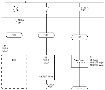
Modify distribution equipment and feeder graphics on the single-line diagram.
Start in the SINGLE-LINE DIAGRAM drafting view.
Modify Distribution Equipment Graphics
-
Run the
ElectroBIM Single-Line→ command. Add/Modify Graphic
 -
Select panel P. The Modify Graphic dialog box will open.
-
Set Single-Line Diagram Graphic ☰ to Panel with Bus, Fed from Top.
-
Set Single-Line Diagram Type ☰ to Dashed.
-
Press the button to close the dialog box.
The graphic for panel P will be updated.
-
Select to use the default tags and tag locations for the graphic.
-
Select the "P" label on the drafting view.
-
Using the Properties panel, set the tag to DME-TAG-Panel-Name_Bus Size_Disconnect-C.
-
Use the grip provided to move the label.
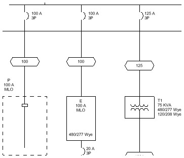
Modify Feeder Graphics
-
Run the
ElectroBIM Single-Line→ command. Add/Modify Graphic -
On the feeder between panel MDP and panel P, select a point between the OCP graphic and feeder ID graphic.
-
Select . The Select Feeder Graphic dialog box will open.
-
Set Group ▾ to Meter.
-
Press the button to close the dialog box. A meter graphic will be added to the feeder at the point you specified.
-
Run the
ElectroBIM Single-Line→ command. Graphic Move
 -
Select the meter graphic, then the OCP graphic. The graphics will change places along the feeder.
-
Run the
ElectroBIM Single-Line→ command. Add/Modify Graphic -
On the feeder between panel MDP and panel E, select the OCP graphic.
-
Select . The Select OCP Graphic dialog box will open.
-
Set Group ▾ to Switch.
-
Press the button to close the dialog box.
The OCP graphic on the feeder will be updated.