Released August 27, 2012
The following is a list of new and updated features in Design Master Electrical 8.2. The requests from our public wish list are highlighted.
The new DM Electrical->Utilities->Merge Project command is used to merge panels and drawings from one project into another project. Devices that are circuited on the drawing that is merged will be transfered to the appropriate panel in the new project. (Requested on the wish list.)
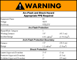
 Arc-Flash
The calculated fault at each panel can be used to calculate the arc-flash values. The incident energy at the working distance and the arc-flash-protection boundary values are calculated and can be displayed in a schedule on the drawing or printed as warning labels to be attached to the panels in the field. (Requested on the wish list.)
Set Equipment Load in Amps: There is a new Set Load in Amps button that can be used to set the load on a piece of equipment in amps. A second dialog will appear where you enter the load in amps. The load will be converted to kVA and set in the equipment dialog box. (Requested on the wish list.)
Subscripts on Low Voltage Devices: Low voltage devices can have subscripts included on them like receptacles. These subscripts can be displayed in the low voltage device schedule.
Primary UPS Voltage: UPS's can have a primary voltage set that is different from the secondary voltage. Setting the primary voltage directly in the UPS saves you from having to insert a separate transformer to model the transformer included in the UPS. (Requested on the wish list.)
Breaker and Conductor Sizing per NEC 440: Equipment breakers and conductors can be sized based upon NEC 440.
The options for Breaker Size are:
The options for Wire Size are:
Switch Subscript Rotation: Added option to force switch subscripts to be drawn right-side up, even when matched to the rotation angle of the switch. Use the DM Electrical->Customizaiton->Options, Switches->Allow upside down switch subscripts option to control this setting.
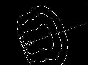
 Light Fixture Contour Overlay: Photometric contour overlays can be generated for light fixtures to help you visualize where the light from the fixture will be cast. The DM Electrical->Customization->Options, Light Fixtures->Display light fixture overlay option controls when the overlay is displayed. (Requested on the wish list.)
The light fixture overlay is only generated for fixtures that have sufficient photometric information defined about them. Either the General Photometrics checkbox or Egress Photometrics checkbox need to be checked. The Elevation needs to be set higher than 0. An IES file needs to be associated with the fixture callout.
The contours in the overlay are based upon the general lighting contour levels. You can change these using the DM Electrical->Customization->Options->Contour level options.
Load IES File Information into Light Fixture Schedule: The text information contained in an IES file can be used to populate the information for a light fixture type in the light fixture schedule using the new Load IES File Information into Schedule button. All of the information in the IES file will be loaded into the schedule. The information the IES file contains varies depending upon what the manufacturer provides. You will need to review the information that is loaded to confirm it is loaded in the correct field and contains useful text. (Requested on the wish list.)
Photometric Area Elevation: The elevation of photometric areas can be set. The elevation can be used to calculate the lighting level at the workspace height or at the floor elevaiton of a raised area.
Sloped Photometric Areas: Photometric areas can be sloped to model stairs.
Calculate Single Area: If more than one area is on the drawing, you will be prompted to select the area to calculate. You can also choose to calculate all of the areas on the drawing.
Rotate IES File Relative to the Fixture: The IES file can be rotated relative to the fixture for times when the light fixture block and the IES file do not point in the same direction.
IES Files Copied to Project Folder: When an IES file is selected for a fixture in a project, a copy of the file is placed in the project folder.
Feeder Lengths on Voltage Drop Schedule: A new column that displays the feeder length is available to be inserted in the voltage drop schedule.
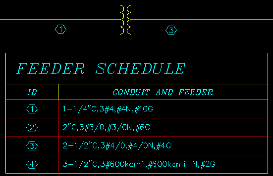
Feeder Schedule Tags: Each line in the feeder schedule can be assigned an ID that can then be used to label feeders on the one-line diagram. (Requested on the wishlist.)

Panel Load in VA or Amps: The loads on a panel can be displayed in VA or amps, in addition to kVA. (Requested on the wish list.)
Panel Schedule Volts and Phase: A new attribute that displays the volts and phase (as either 1-PH or 3-PH) is available to be inserted in panel schedules.
Equipment Schedule Volts and Phase: A new column that displays the volts and phase (as either 1-PH or 3-PH) is available to be inserted on the equipment schedule.
Import Multiple Items: You can import multiple items from the master schedule to the project schedule when using the Import from Master Schedule button. (Requested on the wish list.)
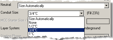
Conduit Fill Percentage Display: The conduit fill percentage is displayed next the Conduit Size field in the dialog boxes where it exists. Changing the conduit size will update the fill percentage.

Homerun Arrowhead: Homerun arrowheads are now drawn with a block instead of as part of a polyline. Using dashed linetypes on homeruns will no longer dash the arrowheads. You can also customize the appearance of the arrowhead if you desire.
Ignore Extra Feeder Length: The calculated distance between two panels includes an additional length of wire to account for terminating the wires. The additional wire length is not necessary on panels that are close to each other. It can now be turned off on feeders that are shorter than a certain distance using the DM Electrical->Customization->Options, One-Line Diagram->Ignore extra length on feeders shorter than this option. (Requested on the wish list.)
Provide Neutral Wires to Switches: 2011 NEC 404.2(C) requires a neutral wire to be provided for switches. The new DM Electrical->Customization->Options, Provide neutral wires to switches option to insert these additional wires when inserting tick marks on your loops.
Copy Room: You can now copy rooms on the drawing using standard AutoCAD commands.(Requested on the wish list.)
Zoom to Schedule: When a schedule is inserted, a Zoom to Schedule After Insertion checkbox is included when inserting a schedule. If this box is checked and the schedule is already inserted on the drawing, you will be moved to the location of the schedule on the drawing. Never lose a schedule on a busy drawing again!
Schedule Column Justification: Each column in a schedule can have its justification individually set to left, center, or right. Previously, all columns were left-justified. To change the column justification, press the Edit Title, Column Labels, and Column Order button when inserting the schedule.
Schedule Title and Column Label Justification: The justification of schedule titles and schedule column labels can be set using the Options command. Go to DM Electrical->Customization->Options and look for the Schedule title justification and Schedule column label justification entries in the Schedules section. The justification can be set to left or center.
Copy or Backup Project: The new Copy of Backup Project command can be used to make a complete copy or backup of the current project. When you copy or backup a project, it is important to copy all of the drawings and the DM database files. This command will take care of copying all the files necessary. Use this command if you want to make a backup of the current state of the project or if you want to make a copy to try a different design idea on.
Copy Drawing and Remove Links to Database: The new Copy Drawing and Remove Links to Database command will copy the current drawing, remove all the links between the DM entities on the drawing and the database, but will not remove any of the DM entities. The copied drawing will look exactly like the original, but will not have any DM intelligence included with it. You can then use standard AutoCAD drafting commands to modify the drawing.
Rename Database: The Rename Database command will change the name of the database file associated with the current drawing. It will change the suffix of the file when viewed in Windows Explorer. Nothing else in the project will be changed.