Released April 28, 2014.
The following is a list of new and updated features in Design Master Electrical 8.3. The requests from our public wish list are highlighted.
We added all of the load calculation options from NEC 220 that were previously missing from the software. You can do any type of feeder or service calculation allowed by the NEC. (Requested on the wish list.) (Requested again on the wish list.)
Load Calculation Method: Each panel or other one-line device has a setting for what load calculation method to use.
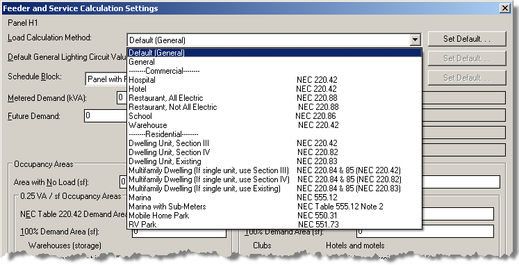
General Lighting Calculations: Lighting load can be calculated based upon the area served by the panel.

Metered Demand and Future Demand: A metered demand value can be specified for each panel or other one-line device.
A future demand value can also be specified, either as a specific value or a percentage of the panel load.
The metered demand and future demand are included in the total load on the panel, but are not shown on a specific circuit.

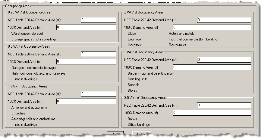
Occupancy Areas: The area served by each panel or other one-line device can be specified and used to calculate the general lighting load. These areas are also used in some of the other calculation methods. The areas are added together as you move up the one-line diagram, so the total area on the main service panel is the sum of the areas of the panels connected to it.
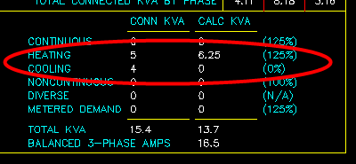
Cooling Load Type: A cooling load type was added. In general, the larger of the heating or cooling load type is used for the calculated load on the panel.
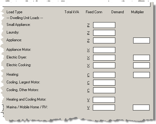
Dwelling Unit Load Types: Multiple load types to support dwelling units were added.
Recurring Panels: Recurring panels are a new type of one-line device. They allow you to create and circuit a panel, then insert multiple instances of it on your drawings. It is intended to be used for hotels and multifamily dwellings that have common room or unit layouts. You design a typical unit and connect all the devices to the recurring panel. Then you insert an instance of the recurring panels for each unit on the drawing. When you need to make changes to the unit design, you modify the typical unit and all the instances are updated automatically.
Meter Centers: Meter centers are a new type of one-line device. Their circuits are labeled sequentially (not split into an odd an even side). The circuits are all two-pole and their starting phase rotates automatically.
UPS Phase Converters: The voltage on a UPS can change from single-phase to three-phase to allow you to model phase converters.
Copy Fixed Loads When Copying a Panel: When you copy a panel or other one-line device, you will be given an option to copy the fixed loads to the new panel.
Do Not List Neutral Wire Separate from Hot Wires: For wire callouts, when the neutral and hot wires are the same size, there is now an option to combine them. Instead of a wire callout of 1/2"C,3#12,#12N,#12G, it would list 1/2"C,4#12,#12G. Use the DM Electrical->Customization->Options, Circuits Load Types, and Wire Sizes->Display neutral wire count separately from phase wire count option to change this setting.
Homeruns from Panels: Homeruns can be inserted on panels and other one-line devices. The circuit callout displays where the panel is fed from. The wire callout displays the feeder size of the panel.
Circuit Description Sorting: When multiple devices are connected to a circuit, their descriptions are sorted alphabetically.
Circuit Description Prefix, Suffix, and Replacement: Custom circuit descriptions are now more flexible. You can add text to the start or the end of the description. You can also set a value that completely replaces the circuit description. In the Circuiting dialog box, the Description field sets a value that is displayed at the start of the circuit description. To set a value at the end or as a replacement, press the More button next to it. It will open a dialog box that allows you to set the other values.

Merge Circuits: The Swap and Copy Circuits command has been renamed to Move Circuits. It now includes a command to merge two circuits. All the devices connected to one circuit and the fixed loads on it will be transfered to the other circuit. (Requested on the wish list.)

Homeruns Wire Callouts and Tick Marks Settings: Two new options have been added for inserting wire callouts and tick marks on homeruns. Tick marks for all homeruns will insert tick marks on all homeruns regardless of the wire size. Nothing for #12, wire callouts if > #12 will insert nothing on homeruns that are #12 and will display full wire callouts for homeruns larger than that. Use the DM Electrical->Customization->Options, Homeruns and Loops->Homerun wire callouts and tick marks option to change this setting.
Multiple Homeruns on a Circuit: You can insert multiple homeruns on a circuit, rather than just one. Insert the first homerun using the normal commands. Use the Draw Additional Homerun command to add more homeruns. You will have to manually add and remove loops as necessary based upon the homeruns you insert. (Requested on the wish list.)
Tandem Breakers: You can now create tandem breakers, also known as twin breakers or peanut breakers. Use the Create Tandem Breaker and Remove Tandem Breaker buttons in the Circuiting dialog box to create them. (Requested on the wish list.)

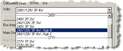
High C-Leg for High-Leg Delta: You can choose whether your high-leg delta panels have a high B leg or a high C leg. You make this choice when selecting the voltage, either 240/120V 3P 4W, High B or 240/120V 3P 4W, High C.
New Circuiting Dialog Box Layout: The layout of the circuiting dialog box has been updated. We tried to keep the spirit of the dialog box the same as before while improving the readability and adding support for the new features in this release.
The top-left now lists only the currently selected panel or one-line device. All of the information about the current circuit has been moved to the right. All the fixed load values are in a separate dialog box that can be accessed using the Set Fixed Loads button.
If you use keyboard shortcuts, press the ALT key to see the shortcuts available for the buttons on the dialog box. You might find these shortcuts helpful if you spend a lot of time in this dialog box.
You can compare the old circuit dialog box with the new one using the images below. Click on the image to view a full version of the dialog box. The old dialog box is on the left and the new one is on the right.
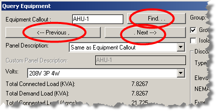
Equipment Navigation Buttons: Three new buttons--Find, Previous, and Next--were added to the Query Equipment dialog box. These buttons can be used to navigate to other equipment in the project. (Requested on the wish list.)
Edit Multiple Equipment: A new Edit Multiple Equipment command was added. You can select multiple pieces of equipment from a list or from the drawing and then make changes to all of them at the same time. (Requested on the wish list.)
Different Equipment Callouts for Groups: An equipment callout setting was added to equipment groups. Using this setting, you can change the callout for each group to look different. (Requested on the wish list.)
New Equipment Callout Commands: Two new commands were added for modifying callouts for individual pieces of equipment. The Modify Equipment Callout command allows you to select a different callout style for a single piece of equipment. The Remove Equipment Callout command allows you to remove the callout from a piece of equipment.
New Light Fixture Schedule Columns: Added new columns related to settings for photometrics to the light fixture schedule. The new columns are Lumens / Lamp, Total Lumens, Egress Mode Lumens / Lamp, Egress Mode Total Lumens, Lamp Depreciation, IES File Name, IES File Name and Path, and Arm Length. (Requested on the wish list.)
Default Mounting Height: Added a default mounting height to light fixtures. This value can be set in the schedule. When a light fixture is inserted that has a default mounting height, the elevation setting will be set to the default value automatically. You can override the default mounting height when the light fixture is inserted or when querying it. A new Default Elevation column was added to the schedule that can display the value. (Requested on the wish list.)
Export to COMCheck: Light fixture quantities and building areas can be exported to COMCheck. (Requested on the wish list.)
Array Device Commands: Added two commands to array devices. They array command was changed in AutoCAD 2012 in a way that it no longer worked with our software. These new commands were added to allow you to continue to array devices in newer versions of AutoCAD. Both array commands are single dimension arrays. If you need to array in two dimensions, run the command twice.
Both commands work in a similar manner. You select one or more devices to array. You provide a distance and an angle. Then you enter the number of devices in the array. The difference between the two is how the distance provided is used.
Improved Edit Multiple Commands: The Edit Multiple commands for all devices have been improved to be more user-friendly. When you select multiple devices, the commands will list the attributes that are the same and that vary and allow you to easily change them.
Arc-Flash Input Units: The input units for all values related to arc-flash have been changed from metric to imperial. Distances are input based upon inches. Energy is input based upon calories / cm2.
Arc-Flash Schedule Display Units: New columns were added to the arc-flash schedule that allow you to display values in either metric or imperial units.
Time-Current Curve File: A file can be attached to each panel or other one-line device in the Arc-Flash dialog. The file is intended to be a way to store the time-current curve file that you used to determine the arcing time. The file is for your reference only. It is not used to calculate the arcing time and is not displayed anywhere else. There is a command to open the file to allow you to easily review it. (Requested on wish list.)
Project Groups: Groups were added to all schedules. Each group is a separate set of a type of device and has its own separate schedule. The most common use for the groups is to allow you to create separate schedules for different types of a device. For example, you could create a general light fixture group and an outdoor light fixture group. The outdoor light fixture group would have a separate schedule that could be inserted on the site plan to document only the fixture types that are used there. (Requested on the wish list.)
Photometric Contour Colors: The color of contours inserted during photometric calculations can be set manually to allow you to more easily differentiate between them.
Export 3D-BIM to DWG File: Three new commands were added to export the 3D model to a DWG file instead of an IFC file.
One-Line Diagram Scaling: The scale command works correctly with devices in the one-line diagram. The block size will remain the same after scaling and not be changed when the one-line diagram is updated.
One-Line Diagram Template Blocks: A new type of one-line diagram block, which we call a template block, has been added. The template block includes the location and settings for the labels in addition to the block itself.
To create a template block, insert a one-line diagram block or panel. Insert labels on the block or panel, including prefix and suffix values if desired. Once everything is set correctly, run the DM Electrical->Customization->Block Creation->Create One-Line Block for One-Line Diagram command. Select the block.
A block will be created and added to your block list. When the block is inserted, the labels will be inserted and filled out at the same time.
Utility Fault One-Line Label: Added a label to panels on the one-line diagram that is the fault from the utility that does not include any motor contributions.
Filter Takeoffs by Layer System: The takeoff quantities can be set to include or exclude specific layer systems.